Skip to content
Electrical to Light Energy: Occurs in appliances like electric bulbs.Electrical to Heat Energy: Occurs in appliances like geysers.
Subatomic Particles: An atom consists of three primary particles:Protons: Positively charged particles.Neutrons: Neutral particles (carrying no charge).Electrons: Negatively charged particles.The Nucleus: Located at the center of the atom, it contains tightly bound protons and neutrons.Orbits: Electrons constantly revolve around the nucleus in fixed paths called orbits.Free Electrons and Current: The flow of electric charge is driven by the movement of free electrons moving in a specific, uniform direction. This flow from a region of excess electrons to a region deficient in electrons constitutes an electric current.
Definition: Electric current is the rate of flow of electric charge through a conductor per unit of time.SI Units:Electric Charge (  ): Measured in Coulomb (
  ).Electric Current (
  ): Measured in Ampere (
  ). One Ampere is defined as the flow of one Coulomb of charge through a conductor in one second (
  ).
).
 = Electric current (in Amperes, ) = Electric charge (in Coulombs, )
  = Time (in seconds,
  )
)
High vs. Low Potential:A high potential region is created by an accumulation of electrons, resulting in a large repulsive force.A low potential region contains fewer or no electrons, resulting in a low repulsive force.This difference in concentration sets free electrons into motion, creating an electric current. Thus, current can only flow if a potential difference exists between two points.Work-Based Definition: Potential difference is the work done in moving a unit charge from one point to another.SI Unit: Measured in Volt (  ), named in honor of the Italian physicist Alessandro Volta.1 Volt is the potential difference produced when 1 Joule of work is done to move 1 Coulomb of charge.

 Practical Example: A standard torch cell has a positive (
  ) terminal and a negative (
  ) terminal. When connected in a closed circuit, the potential difference between these terminals drives the current, causing the bulb to glow.
Electron Flow: Electrons, being negatively charged, flow from a point of excess (the negative terminal) to a point of deficiency (the positive terminal).Conventional Current: By established historical convention, the direction of electric current is taken as flowing from the positive terminal of the battery, through the circuit components, to the negative terminal.Key Takeaway: The direction of conventional current is always opposite to the direction of actual electron flow.
Anode (Positive Electrode): A central carbon rod topped with a brass cap.Cathode (Negative Electrode): A zinc container that also serves as the outer protective casing.Depolarizer Mixture: A mixture of manganese dioxide (  ) and carbon (
  ) packed inside a muslin bag surrounding the carbon rod.Electrolyte: A moist, thick paste of ammonium chloride (
  ) and plaster of Paris.Insulation: The outer sides of the zinc container are covered with thick cardboard or plastic, leaving only the metal bottom exposed as the negative terminal.
Series Connection: The positive terminal of the first cell is connected to the negative terminal of the next. This increases the total available electrical voltage.Also Known As: Rechargeable secondary batteries are often called storage cells or accumulators.
The Mains: Domestic electricity is generated at large power stations and sent through high-voltage transformers and overhead or underground cables to reach the main panel of our homes.Generators & Dynamos: Devices that convert mechanical energy into electrical energy by rotating a conductor (like copper wire) within a strong magnetic field.Hydroelectric Power: Turbines are spun by flowing water.Thermal Power: Turbines are spun by steam produced by burning fossil fuels (coal, diesel, natural gas).Nuclear/Atomic Power: Nuclear energy is harnessed to generate steam and spin turbines.Domestic Generators: Small standby generators use diesel or kerosene.Solar Cells: Devices that convert solar (light) energy directly into electrical energy.Solar Panels: Large arrays of interconnected solar cells.Applications: Calculated devices, streetlights, space stations, and artificial satellites.Wind Energy: High-speed wind rotates the blades of a windmill, which turns an internal generator to produce clean electricity.
Initiative: The Jawaharlal Nehru National Solar Mission, launched in 2010 by the Government of India, promotes green, ecologically sustainable growth under the National Action Plan on Climate Change.Milestones:The original target was to achieve  of solar power by 2022.This target was surpassed in 2018, four years ahead of schedule.The goal was subsequently updated to
  of grid-connected solar power.India’s solar capacity surged from a mere
  in 2010 to
  by 2021.Global Connection: This initiative aligns directly with the United Nations Sustainable Development Goal 7 (SDG 7: Affordable and Clean Energy).
Georges Leclanché (1839–1882): A French scientist celebrated for inventing the Leclanché cell in 1866.Significance: His cell utilized an electrolyte of ammonium chloride, a zinc electrode, and a carbon/manganese dioxide mixture. These exact materials laid the chemical foundation for the modern dry cell.
Closed (Complete) Circuit: When the switch is ON, there are no breaks in the path. Current flows continuously, allowing connected appliances (like a bulb) to function.Open (Incomplete) Circuit: When the switch is OFF or any wire connection is broken, the electrical path is interrupted. No current can flow, and appliances stop working.
Single Loop: The same current flows through every component sequentially.Voltage Sharing: The total supply voltage is divided among the connected appliances.Interdependence: All appliances depend on one another to complete the circuit. If one bulb gets damaged (fused filament) or is removed, the entire circuit is broken, and all other appliances instantly stop working.
Multiple Branches: The current splits into different branches.Full Voltage: Each appliance receives the full, original voltage of the power source.Independence: Each branch operates independently with its own switch. If one appliance is switched off, damaged, or removed, the other branches remain complete, and those appliances continue to work normally.
Resistance: The property of a material to oppose or limit the flow of electric current.Resistors: Specially designed electrical components placed in circuits to regulate and control the amount of current flowing through various paths.
Conductors: Materials that offer very low resistance, allowing electric current to flow through them easily.Examples: Metals like copper, silver, nickel, aluminum, iron, and steel.Biological & Liquid Conductors: The human body and impure water (tap water) also conduct electricity.Application: Copper is widely used to make electrical wires due to its high conductivity.Insulators (Non-Conductors): Materials that offer extremely high resistance, preventing the flow of electric current.Examples: Plastic, rubber, wood, glass, ceramics, cotton, paper, and pure (distilled) water.Air as an Insulator: Air is a natural insulator, which is why current does not leap across broken gaps in a circuit under normal conditions.Application: Electric wires are coated in plastic or rubber to protect users from electric shocks.Myth: All outdoor overhead power lines are safely insulated.Fact: Approximately 90% of outdoor power lines are bare, uninsulated wires. They may feature a weather-resistant coating, but it provides absolutely no protection against electric shock. Never touch or get close to outdoor power lines.
Avoid Wet Hands: Never touch electrical switches, appliances, or sockets with wet hands. Tap water is a conductor; wet skin dramatically lowers electrical resistance, allowing current to flow easily through your body.Professional Repairs: Never attempt to repair electrical appliances yourself; always hire a qualified technician.Secure Plugs: Ensure plugs fit tightly into sockets. Loose connections cause dangerous sparking, which can burn the socket or start a fire.No Bare Sockets/Wires: Do not touch active metal parts of appliances. Cover all exposed wires with high-quality insulating tape.Quality Certification: Only purchase electrical wires and appliances carrying the official ISI mark, which ensures safety compliance.Use Insulated Stands: Stand on a dry rubber mat or wooden board when handling electrical maintenance or repairs.Emergency Shutoff: Immediately turn off the main circuit breaker/switch in the event of a short circuit, sparking, or an electrical fire.
A safety device containing a thin wire with a low melting point.When current exceeds safe limits, the wire overheats, melts, and breaks the circuit.Drawback: It is a single-use device; the melted fuse wire must be manually replaced every time an overload occurs.
Share
Explore
 Self Study
Prepared by: learnloophq@gmail.com
Chapter: 07. Electricity
Introduction to Electricity & Atomic Structure
Electricity is a highly versatile form of energy generated in electric power plants and transmitted to homes, schools, and industries. It can be easily converted into other energy forms to power everyday appliances:
1. Atomic Structure and Electric Charge
All materials are composed of tiny, fundamental particles called atoms. The behavior of electricity is deeply rooted in the structure of these atoms.
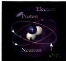
Fig: Structure of an atom
Fig: Structure of an atom
2. Electric Current and Its Mathematical Relation
Mathematical Formula:
Where:
PlantUML Mindmap: Atomic Structure & Current Basics

Potential Difference & Current Flow Direction
To make an electric current flow through a conductor, there must be a push or pressure difference, known as a potential difference.
1. Understanding Potential Difference
Mathematical Formula:
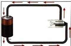
Fig: Potential difference between cell terminals drives electric current
Fig: Potential difference between cell terminals drives electric current
2. Direction of Current Flow
When analyzing circuits, we distinguish between electron movement and conventional current direction:
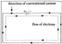
Fig: Direction of conventional current vs. electron flow
Fig: Direction of conventional current vs. electron flow
PlantUML Mindmap: Potential Difference & Current Direction

Sources of Electricity
Electric current can be generated from various chemical, mechanical, and light-based sources. These include electric cells, batteries, generators, and solar cells.
1. Electrochemical Cells (Electric Cells)
An electrochemical cell is a device that converts chemical energy into electrical energy through internal chemical reactions.
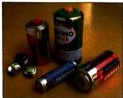
Fig: Different kinds of cells
Fig: Different kinds of cells
Cells are broadly classified into two categories:
Feature
Primary Cell
Secondary Cell
Chemical Reaction
Irreversible (cannot be reversed)
Reversible (can be run backward)
Rechargeability
Cannot be recharged; discarded after use
Can be recharged and reused multiple times
Applications
Small devices: torches, toys, wall clocks, calculators, radios
Mobile phones, digital cameras, laptops, automobiles, emergency lights
Examples
Dry cell, Simple Voltaic cell, Daniel cell, Leclanche cell
Lead-acid accumulator, Edison accumulator, Nickel-iron accumulator
2. The Primary Dry Cell
Developed in 1887 by Yai Sakizo of Japan, the dry cell is a highly portable, leak-proof primary cell.
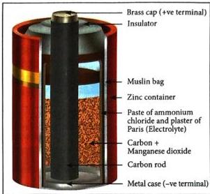
Fig: Structural cross-section of a dry cell
Fig: Structural cross-section of a dry cell
Construction and Materials:
Science Alive! Despite its name, a dry cell is not entirely dry; the electrolyte is a moist paste containing a small amount of water. Liquid-electrolyte cells, by contrast, use fluid solutions. Never attempt to pry open a dry cell—its internal chemicals are toxic and must be disposed of safely.
3. Batteries
A single cell provides a limited amount of electric potential (typically  ). To power heavy-duty appliances or vehicles, multiple cells are connected together in series to form a battery.
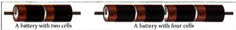
Fig: Two-cell and four-cell batteries
Fig: Two-cell and four-cell batteries
4. Other Major Sources of Electricity
Case Study: Clean Energy & India’s Solar Journey
Science and Scientists: Georges Leclanché
PlantUML Mindmap: Sources of Electricity

Electric Circuits & Circuit Diagrams
An electric circuit is a complete, unbroken path through which electric current flows.
1. Components of an Electric Circuit
An electric circuit is composed of several key elements, each performing a specific function:
Component Name
Standard Symbol
Primary Function
Cell
—[
Source of electric current (single unit).
Battery
—[—[
Source of electric current (multiple cells in series).
Connecting Wire
—————
Provides a continuous path for current flow.
Open Switch
— \ —
Interrupts (breaks) the circuit; stops current flow.
Closed Switch
— • —
Completes the circuit; allows current flow.
Open Plug Key
— ( ) —
Keeps a circuit open for longer durations.
Closed Plug Key
— ( • ) —
Keeps a circuit closed for longer durations.
Electric Bulb
—(⚙)—
Converts electrical energy to light; indicates active current.
Resistor
—///\—
Opposes and regulates the flow of current.
2. Closed vs. Open Circuits
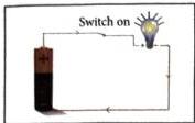
Fig: A complete, closed circuit (bulb glows)
Fig: A complete, closed circuit (bulb glows)
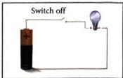
Fig: An incomplete, open circuit (bulb does not glow)
Fig: An incomplete, open circuit (bulb does not glow)
PlantUML Mindmap: Circuits & Diagrams

Series and Parallel Circuits
There are two primary ways of connecting multiple electrical components in a circuit: series and parallel connections.
1. Series Circuits
In a series circuit, all components are connected end-to-end, forming a single path for the flow of electric current.
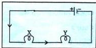
Fig: Bulbs connected in a series circuit
Fig: Bulbs connected in a series circuit
Characteristics of Series Circuits:
2. Parallel Circuits
In a parallel circuit, components are connected across common points, creating multiple parallel paths for the current.
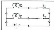
Fig: Bulbs connected in a parallel circuit
Fig: Bulbs connected in a parallel circuit
Characteristics of Parallel Circuits:
Comparison: Series vs. Parallel Circuits
Feature
Series Circuit
Parallel Circuit
Current Path
Single path for current
Multiple paths for current
Voltage Distribution
Shared among components (dimmer bulbs)
Each component receives full voltage (brighter bulbs)
Independence
Highly dependent; one failure turns off everything
Independent; one failure does not affect others
Control
Single master switch controls all components
Each appliance can have its own individual switch
Household Wiring
Not used (impractical)
Standard method used in homes
PlantUML Mindmap: Series vs. Parallel

Conductors, Insulators & Resistors
Materials respond differently to the flow of electric charge. They are categorized based on their level of resistance to electrical current.
1. Resistors and Resistance
2. Conductors vs. Insulators
Materials are classified based on how easily they allow electrons to pass through them:
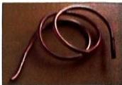
Fig: Copper—an excellent electrical conductor
Fig: Copper—an excellent electrical conductor

Fig: Plastic coating—protects as an insulator
Fig: Plastic coating—protects as an insulator
Myth vs. Fact
PlantUML Mindmap: Conductors & Insulators

Safety Precautions & Modern Safety Devices
Using electricity requires strict safety standards. Standard domestic circuits feature safeguards to prevent fire, short circuits, and electric shocks.
1. Crucial Electrical Safety Rules
2. Advanced Circuit Protection: Fuses vs. MCBs
To protect homes and appliances from sudden power surges or short circuits, specialized safety cut-off devices are installed:
The Electric Fuse
Want to print your doc?
This is not the way.
This is not the way.

Try clicking the ··· in the right corner or using a keyboard shortcut (
CtrlP
) instead.