Skip to content
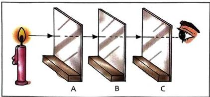
The Setup: Three cardboards (A, B, and C) with small holes are placed in sequence.The Observation: A student can see the light passing through the holes only when they are perfectly aligned. When cardboard C is moved slightly out of alignment, the light is immediately blocked, and the student can no longer see it.The Inference: While the source text presents this as a question without explicitly stating the answer, this classic experiment demonstrates that light travels in a straight line (rectilinear propagation).
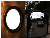
Plane Mirrors: Mirrors with a flat, highly polished reflecting surface. Used primarily for personal grooming.Spherical Mirrors: Curved mirrors. Used in applications like vehicle rear-view mirrors to observe oncoming traffic from behind.
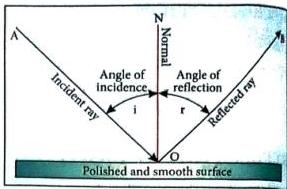
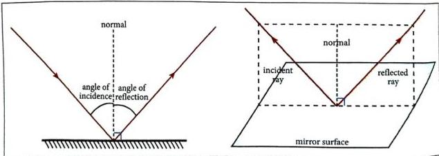
First Law: The incident ray, the reflected ray, and the normal at the point of incidence all lie in the same plane.Second Law: The angle of incidence is always equal to the angle of reflection (Angle i = Angle r).
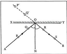
Aim: To verify the two laws of reflection using a plane mirror setup.Materials Required: A drawing board, a white sheet of paper, board pins, a plane mirror, a plane mirror holder, a protractor, a pencil, and a ruler.Procedure:Fix the white sheet of paper on the drawing board using board pins.Draw a straight line XY to mark the position of the mirror and place the plane mirror vertically on this line using the holder.Fix two board pins vertically on the paper at points P and Q in front of the mirror.Look into the mirror from the other side and fix two more pins vertically at points R and S such that they are in a perfect straight line with the images of the first two pins (P’ and Q’).Remove the pins and mark their positions.Draw line AO passing through P and Q (incident ray), and line BO passing through R and S (reflected ray).Draw a line ON perpendicular to XY at the point of incidence O (the normal).Use a protractor to measure the angle of incidence ∠AON and the angle of reflection ∠BON.Observation: The angle of incidence ∠AON is exactly equal to the angle of reflection ∠BON. Additionally, the incident ray, reflected ray, and normal all lie flat on the paper sheet.Conclusion: The laws of reflection are verified experimentally.
Definition: The phenomenon in which the right side of an object appears as the left side in its image, and vice versa, is called lateral inversion.
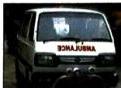
On ambulance vans, the word “AMBULANCE” is painted in" its laterally inverted form as  .Purpose: This is done so that drivers of vehicles" ahead of the ambulance can read the word the correct way around (“AMBULANCE”) when looking into their rear-view mirrors," allowing them to quickly give way to the emergency vehicle.
Light rays diverge from the point source O in all directions.For tracing, take two incident rays OA and OC.These rays strike the mirror and reflect as rays AB and CD respectively, entering the observer’s eye.When the reflected rays AB and CD are extended backwards behind the mirror, they appear to meet at point I.Point I is the virtual image of the point object O.Object Distance vs. Image Distance: Measuring the distance shows that OP = IP. The distance of the object from the mirror is exactly equal to the distance of its image behind the mirror.
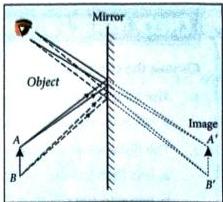
Rays of light travel from all points on the object. Tracing two rays from the extreme top point A shows they reflect and appear to diverge from a point A’ behind the mirror.Similarly, tracing rays from the bottom extreme point B shows they reflect and appear to diverge from point B’ behind the mirror.The complete image A’B’ is formed.This image is identical in size to the object AB, is located at an equal distance behind the mirror, and is laterally inverted.
The size of the image is equal to the size of the object.The image is laterally inverted.The distance between the image and the mirror is equal to the distance between the object and the mirror.

Used as standard makeup mirrors and looking glasses.Used in barber shops to show the front and back of the head.Placed on opposite walls of a room to make small rooms look visually spacious.Used in scientific laboratories.Used in solar cookers and solar geysers to reflect and focus sunlight.Used to construct optical instruments like periscopes and kaleidoscopes.
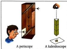
Periscope: A long, vertical tube containing a set of mirrors aligned at angles (typically 45°) that enables you to view objects above your direct line of sight.Applications: Used in submarines to view objects above the water surface; used by tank commanders to observe enemy movements around them without exposing themselves.Kaleidoscope: A cylindrical tube containing multiple mirrors arranged at angles. It is used to generate beautiful, colorful, and highly symmetrical patterns when viewed from one end.

Sunlight Travel Time: It takes about 8 minutes for light emitted from the Sun to reach Earth.Speed in Vacuum/Air: Exactly 29,97,92,458 meters per second (often rounded to approximately 3 × 10⁸ m/s).Speed in Mediums: Light slows down when traveling through transparent mediums.Refractive Index: The ratio by which light is slowed down in a transparent material is called the refractive index of that medium.
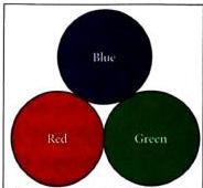
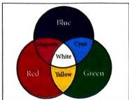
Definition: Colors of light that cannot be obtained by mixing any other colors, but can be mixed together to produce all other colors.The Three Primary Colours: Red, Green, and Blue (RGB), also known as the basic colors of light.Mixing All Three: When Red, Green, and Blue lights are combined in equal measure, they produce white light.
Definition: The colors produced by mixing any two primary colors of light. They are also referred to as composite colors.Key Combinations:Red + Blue = MagentaBlue + Green = CyanRed + Green = Yellow
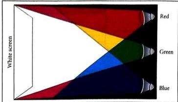
Materials Required: Three torches, cellophane papers of red, green, and blue colors.Procedure: Cover each torch with a different colored cellophane paper (one red, one green, one blue) to generate colored beams. Turn on the torches and focus their beams to overlap on a white wall or screen.Observation: The central overlapping region where all three colored lights intersect appears purely white.
Colorful chemical powders used during festivals like Holi pose safety risks.These synthetic chemical colors can cause severe health hazards to humans and directly contaminate local water bodies, causing severe water pollution.Addressing this issue aligns with the United Nations’ Sustainable Development Goal 13: Climate Action.
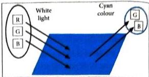
Blue Object: Absorbs all other colors of white light and reflects only blue light.White Object: Reflects all constituent colors of white light and absorbs none.Black Object: Absorbs all colors of white light and reflects none.Red Light on White Paper: The white paper will appear red because only red light is available in the environment to be reflected.
The specific wavelengths of light that the object’s material is capable of reflecting or absorbing.The wavelengths (colors) present in the light source illuminating the object.
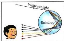
A rainbow is a natural band of colors formed in the atmosphere.It is observed when sunlight emerges immediately after rain.Tiny water droplets suspended in the atmosphere act as natural prisms, splitting the white sunlight into its seven constituent colors via reflection and dispersion.The Seven Colors (VIBGYOR): Violet, Indigo, Blue, Green, Yellow, Orange, and Red.
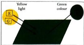
White − Red (absorbed) = (Red + Green + Blue) − Red = Green + Blue = CyanThe shirt reflects green and blue light, making it appear cyan.Yellow − Red (absorbed) = (Red + Green) − Red = GreenThe shirt reflects only green light, making it appear green.
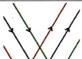
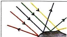
Occurs when parallel rays of light fall on a highly smooth surface (like a mirror).The reflected rays remain perfectly parallel to each other.This type of reflection produces clear, sharp images.
Occurs when parallel rays of light fall on a rough, irregular surface (like cardboard, paper, or leaves).The incident parallel rays are reflected at different angles and in completely different directions.This type of reflection scatters light, allowing us to see objects from any viewing angle.Not a Failure of the Laws of Reflection: Diffused reflection is not a failure of physical laws. Due to the microscopic irregularities of the rough surface, the normal line at each individual point of incidence points in a different direction. Every individual light ray strictly follows the law of reflection (Angle i = Angle r) at its point of contact.
Drivers find it difficult to drive on wet roads at night.Water fills the microscopic rough irregularities on the road surface, making it flat and smooth.This converts the safe, scattered diffused reflection of the road into specular reflection, directing concentrated beams of oncoming car headlights directly into the driver’s eyes as a highly distracting glare.

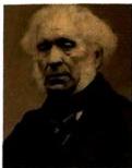
Sir David Brewster was a prominent 19th-century British scientist and philosopher.His main scientific contributions were in the study of light properties.He invented the kaleidoscope in 1816.
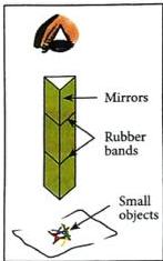
Materials: Three rectangular plane mirrors of equal size, rubber bands, transparent tape, small colored objects (beads, glitter), a piece of white cardboard, and a clear plastic sheet.Procedure:Join the three mirrors together along their long edges to form a triangular prism shape.Secure them tightly using transparent tape and rubber bands.Cut out a triangle from the white cardboard to fit one open end of the prism, make a small viewing hole in its center, and tape it securely.Drop your beads and glitter inside the mirror prism.Cut a triangle from the clear plastic sheet, fit it over the opposite open end, and seal it.Look through the viewing hole toward a light source and slowly rotate it to observe shifting, symmetrical patterns.
The Setup: A circular disc is painted with sections of the seven colors of the rainbow (Violet, Indigo, Blue, Green, Yellow, Orange, and Red).The Phenomenon: When the disc is spun at high speed, the individual colors merge, and the disc appears solid white.
Share
Explore
 Self Study
Prepared by: learnloophq@gmail.com
Chapter: 04. Light
Chapter 4: Light
1. Introduction and Light Propagation
When a mirror is held in the path of sunlight, a round or oval patch of light appears on a ceiling or wall. This occurs because the rays of sunlight strike the mirror and are redirected. This bouncing action is due to the phenomenon known as reflection of light.
The Connect Experiment: Alignment of Light
An experiment demonstrates how light travels through cardboards labeled A, B, and C:

2. Reflection of Light and Classifying Materials
Reflection of light is defined as the bouncing back of light rays into the same medium after striking a surface.
Behavior of Different Materials Under Light
Not all objects reflect light in the same manner. Materials are classified based on how they interact with light:
Material Type
Interaction with Light
Degree of Reflection
Example
Transparent
Lets most of the light pass through it.
Reflects very little light.
Thin clear sheet of glass
Translucent
Lets some light pass through it.
Reflects some of the falling light.
Thick sheet of glass, butter paper
Opaque
Does not let any light pass through it.
Absorbs or reflects most of the light.
Wood, cardboard, metal sheets
Black Opaque
Absorbs almost all light falling on it.
Reflects almost no light.
Black-coated surface
Smooth / Polished
Reflects almost all the light falling on it.
Highly reflective.
A polished mirror
Mirrors
A mirror is a smooth and highly polished surface which reflects most of the light falling on it. Mirrors are broadly classified into two categories:

3. Key Terminology in Reflection
Understanding the behavior of light reflections requires learning key physical terms:
Term
Definition
Diagram Reference (Fig. 4.2)
Incident Ray
The ray of light which strikes the reflecting surface.
Ray AO
Reflected Ray
The ray of light which is reflected back into the same medium after striking the surface.
Ray OB
Point of Incidence
The exact point on the reflecting surface where the incident ray strikes.
Point O
Normal
A perpendicular line drawn to the reflecting surface at the point of incidence.
Line ON
Angle of Incidence
The angle formed between the incident ray and the normal.
Angle ∠AON (denoted as i)
Angle of Reflection
The angle formed between the reflected ray and the normal.
Angle ∠BON (denoted as r)
Plane
The flat surface/boundary containing the incident ray, reflected ray, and normal.
The entire plane of the paper

4. The Laws of Reflection and Experimental Verification
The Two Laws of Reflection
Whenever light rays are reflected from a surface, they strictly obey two fundamental laws:
Activity: Verifying the Laws of Reflection

5. Plane Mirrors and Lateral Inversion
A plane mirror consists of a flat, thin, uniform sheet of glass with one surface polished or silvered to make it opaque and highly reflective.
Lateral Inversion
When you stand in front of a plane mirror and brush your teeth with your right hand, your mirror image appears to brush with the left hand.
Science Alive: Ambulance Vans

6. Image Formation in Plane Mirrors
Image of a Point-Sized Object
Consider a point object O placed in front of a plane mirror PQ such that line OP is perpendicular to PQ:
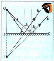
Image of an Extended-Sized Object
Consider a physical object AB of finite height placed in front of a plane mirror:
Core Characteristics of Images Formed by a Plane Mirror
7. Uses of Plane Mirrors and Optical Instruments
General Uses
Special Optical Instruments
8. Speed of Light
The speed of light is a fundamental constant of nature, denoted by the letter c. It is considered the absolute maximum speed limit at which all matter in the universe can travel, as described by Albert Einstein’s Theory of Special Relativity.
Key Facts
Speed of Light in Various Mediums
Medium
Speed of Light
Air or Vacuum
3 × 10⁸ m/s
Water
2.25 × 10⁸ m/s
Glass
2 × 10⁸ m/s

9. Primary and Secondary Colours
White light is not a single independent color; it is a combination of a spectrum of different colors. It can be recreated by combining just three primary frequencies of light which are widely separated on the visible spectrum.
Primary Colours of Light
Secondary Colours of Light
Activity: Recreating White Light using RGB Torches
Eco-Soldier Connection: Festival Powders & Environmental Impact


10. Color Perception and Colour Subtraction
The perceived color of an object does not exist inherently inside the object itself, but is entirely determined by the light reflected from its surface to our eyes.
How Objects Reflect and Absorb Light
When white light falls on an object, some wavelengths (colors) are absorbed and others are reflected:
The Two Determining Factors of Object Color
Formation of a Rainbow
Colour Subtraction
Colour subtraction is the process of determining the final color of an object when a single color or a mixture of" colors is projected onto it. The wavelengths absorbed by the object are “subtracted” from the incoming light.
Example 1:" White Light on a Red-Absorbing Shirt
A shirt is made of material that absorbs red light. If white light (Red + Green + Blue) is cast on it:
Example 2: Yellow Light on a Red-Absorbing Shirt
If yellow light (Red + Green) is cast on the same shirt (which absorbs red):

11. Specular vs. Diffused Reflection
Reflection behavior changes depending on whether the surface is smooth or rough:
Specular (Regular) Reflection
Diffused (Irregular) Reflection
Real-World Application: Night Driving on Wet Roads
12. History, Model-Making, and DIY Activities
Scientific History: Sir David Brewster (1781–1868)
DIY Activity: Making a Kaleidoscope
Cross-Curricular Activity: Newton’s Disc
Want to print your doc?
This is not the way.
This is not the way.

Try clicking the ··· in the right corner or using a keyboard shortcut (
CtrlP
) instead.