Skip to content
Natural Magnets: Magnets that occur naturally in the Earth.Example: Magnetite (Fe₃O₄).Artificial Magnets: Magnets in which magnetic properties have been artificially imparted. They are designed in various shapes depending on their application.Examples: Bar magnets, horseshoe magnets, cylindrical magnets, and magnetic needles.
Attractive Property: A magnet exerts an attractive force on specific metals, known as magnetic materials.Magnetic Materials: Materials strongly attracted by a magnet (e.g., iron, cobalt, steel, and nickel).Non-Magnetic Materials: Materials that show no attraction to a magnet (e.g., glass, wood, plastic, aluminium, copper, and brass).Note on Pole Strength: The magnetic force of a magnet is not uniform; it is always maximum at its poles.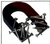
Fig 8.1: A magnet attracting metallic objectsDirective Property: When a magnet is suspended freely, it always aligns itself along the geographic North-South direction.North Pole: The end of the magnet pointing toward the geographic North.South Pole: The end of the magnet pointing toward the geographic South.
Fig 8.1: A magnet attracting metallic objectsDirective Property: When a magnet is suspended freely, it always aligns itself along the geographic North-South direction.North Pole: The end of the magnet pointing toward the geographic North.South Pole: The end of the magnet pointing toward the geographic South.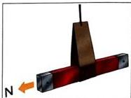
Fig 8.2: Free suspension showing North-South alignmentMagnetic Poles Always Exist in Pairs: It is impossible to isolate a single magnetic pole (monopole).If a bar magnet is broken in half, each individual piece becomes a complete magnet with its own North and South poles.Repeatedly breaking the pieces into smaller bits continues to yield complete magnets, each containing both poles.
Fig 8.2: Free suspension showing North-South alignmentMagnetic Poles Always Exist in Pairs: It is impossible to isolate a single magnetic pole (monopole).If a bar magnet is broken in half, each individual piece becomes a complete magnet with its own North and South poles.Repeatedly breaking the pieces into smaller bits continues to yield complete magnets, each containing both poles.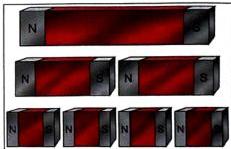
Fig 8.3: Broken magnet pieces forming individual poles
Fig 8.3: Broken magnet pieces forming individual poles
Myth: You can buy or find a magnet with a single isolated pole (either just North or just South).“Fact: Some retail magnets are labeled as just “North” or “South” to indicate which pole is exposed. In reality, the opposite” pole is simply covered with an adhesive, plastic cup, or metal casing, but it still exists.

Like poles repel: When two North poles or two South poles are brought near each other, they push apart.Unlike poles attract: When a North pole and a South pole are brought near each other, they pull together.
Attraction is inconclusive: An unmagnetized magnetic material (like iron, nickel, or cobalt) will be attracted to both the North and South poles of a test magnet.Repulsion is conclusive: Only a magnet can repel another magnet. Therefore, if one end of the unknown bar is attracted to a pole of a test magnet and the other end is repelled, the unknown bar is a magnet. If both ends are attracted, it is merely an unmagnetized magnetic material.
Bar-Shaped Electromagnet: Insulated copper wire is wrapped in a continuous coil around a straight, bar-shaped soft iron core.
Fig 8.9: Bar-shaped electromagnet diagramU-Shaped Electromagnet: Insulated copper wire is wrapped around a U-shaped soft iron core.
Fig 8.9: Bar-shaped electromagnet diagramU-Shaped Electromagnet: Insulated copper wire is wrapped around a U-shaped soft iron core.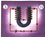
Fig 8.10: U-shaped electromagnet diagramSouth Pole (S): Developed at the end of the coil where the electrical current flows in a clockwise direction.North Pole (N): Developed at the end of the coil where the electrical current flows in an anticlockwise direction.
Fig 8.10: U-shaped electromagnet diagramSouth Pole (S): Developed at the end of the coil where the electrical current flows in a clockwise direction.North Pole (N): Developed at the end of the coil where the electrical current flows in an anticlockwise direction.
Amount of Current Flowing through the Coil: Increasing the electric current strengthens the magnetic field; decreasing the current weakens it.Number of Turns per Unit Length of the Coil: Keeping the length of the core constant, winding more turns of wire around the core increases the strength of the electromagnet.
Electrical Appliances: Found inside telephones, electric motors, and electric bells.Heavy Machinery: Used in industrial cranes to lift and transport heavy scrap iron and steel.Transportation: Powering high-speed magnetic levitation (bullet) trains.Mining & Sorting: Separation of magnetic iron ore from non-magnetic impurities.Medical Procedures: Removing dangerous steel or iron splinters from a patient’s wounds.Industrial Furnaces: Assisting in loading large batches of iron.Manufacturing: Used in the preparation of permanent magnets and magnetic storage media (audio and video tapes).
U-shaped Electromagnet: Provides the temporary magnetic force.Armature: A soft iron bar positioned near the poles of the electromagnet.Contact Screw: An adjustable screw touching the contact spring.Contact Spring: Connects the armature to the electrical circuit.Hammer and Gong: The hammer is attached to the armature and strikes the metallic gong to make sound.Terminals (  and
and  ): Connected to an external battery and push-button switch.
Closing the Circuit: When the push-button switch is pressed, the electric circuit is completed. Current flows from the battery, through the electromagnet, across the contact screw, down the contact spring, and back to the battery.Magnetization and Attraction: As current passes through the U-shaped electromagnet, it becomes highly magnetized. It immediately attracts the soft iron armature.The Strike: As the armature is pulled toward the electromagnet, the attached hammer swings and strikes the gong, producing a loud ringing sound.Breaking the Circuit: The movement of the armature toward the electromagnet pulls the spring away from the contact screw. This physical separation breaks the electrical connection.Demagnetization: Since the circuit is broken, current stops flowing. The electromagnet instantly loses its magnetism and releases the armature.Resetting the Connection: The spring pulls the armature back to its original position, bringing it back into contact with the contact screw.Repetitive Cycle: As soon as contact is restored, the circuit is completed once more. The entire sequence repeats continuously as long as the user keeps the push-button switch pressed down.

Magnet Stationary Outside the Coil: The galvanometer needle remains at zero; no current is induced.Magnet Moved Toward the Coil: The needle deflects in one direction, showing that an electric current has been induced in the coil.Magnet Stationary Inside the Coil: The galvanometer reading immediately drops back to zero; no current is induced when there is no physical motion.Magnet Moved Away from the Coil: The needle deflects again, but in the opposite direction, indicating that an induced current is flowing in the opposite direction.Continuous Motion: Continuous movement of either the magnet or the coil results in continuous, alternating deflections of the needle.
First Law: A current is induced in a coil whenever the number of magnetic lines of force associated with that coil undergoes a change.Second Law: The magnitude of the induced current is directly proportional to the rate at which the magnetic lines of force associated with the coil change.Increase the number of turns of wire in the coil.Increase the strength of the permanent magnet being used.Increase the relative speed of motion between the magnet and the coil.

In 1831, Faraday discovered the principle of electromagnetic induction.His discovery served as the foundation for modern" power generation, enabling the invention of the electric transformer and electric generator.He also developed the physical concept of “”“lines of magnetic force”, which remains a cornerstone of modern physics.
MRI (Magnetic Resonance Imaging):Mechanism: Uses powerful electromagnets, radio waves, and a computer to generate highly detailed images of internal soft tissues, organs, nerves, the brain, and the spinal cord.Safety: There is zero exposure to harmful ionizing radiation.Limitations: It generates a lot of noise, is expensive, and takes a relatively long time. Because of the extremely strong magnetic fields, MRIs cannot be performed on patients with metallic implants (pacemakers, surgical screws, etc.).CT Scan (Computed Tomography):Mechanism: Uses high-energy X-rays to produce cross-sectional images of body structures.Safety: Exposes the patient to radiation.Advantages: It is faster, quieter, and less expensive than an MRI, making it highly preferred for emergency diagnoses.
Share
Explore
 Self Study
Prepared by: learnloophq@gmail.com
Chapter: 08. Magnetism
CHAPTER 8: MAGNETISM — COMPREHENSIVE STUDY NOTES
1. Introduction to Magnets and Their Properties
Magnets are materials that produce magnetic fields and attract certain metals. They can be broadly classified into two categories based on their origin:
Key Properties of Magnets
💡 MYTH VS FACT
2. The Law of Magnetism and Testing Methods
The Law of Magnetism
The fundamental law governing magnetic interactions states:
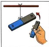
Fig 8.4: Like poles repel
Fig 8.4: Like poles repel
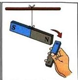
Fig 8.5: Unlike poles attract
Fig 8.5: Unlike poles attract
Test for Magnetism: Repulsion is the Surest Test
To determine whether an unknown metallic bar is a permanent magnet or just a simple magnetic material (like an unmagnetized iron bar), you must test both of its ends against a known magnetic pole:
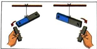
Fig 8.6: Both poles of a magnet attracting an unmagnetized iron bar
Fig 8.6: Both poles of a magnet attracting an unmagnetized iron bar
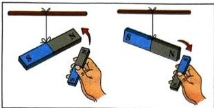
Fig 8.7: Attraction vs Repulsion test showing magnetic properties
Fig 8.7: Attraction vs Repulsion test showing magnetic properties

3. Electromagnetism and Types of Electromagnets
Electromagnetism is the branch of physics that deals with the magnetic effects produced by an electric current.
An electromagnet is a temporary magnet consisting of a soft iron core with an insulated copper wire wound around it. When electric current flows through the coil, the core gets magnetized; as soon as the current is switched off, the core loses its magnetic properties.
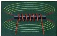
Fig 8.8: Basic electromagnet solenoid field line demonstration
Fig 8.8: Basic electromagnet solenoid field line demonstration
Permanent vs. Temporary Magnets
Permanent Magnets
Temporary Magnets
Retain magnetic properties permanently, even without an external field.
Behave as magnets only when under the influence of a strong magnetic field or current.
Usually made of hard magnetic materials.
Usually made of soft magnetic materials (like soft iron).
Examples: Bar magnets, horseshoe magnets.
Example: Electromagnets.
Types of Electromagnets
Depending on their structural design, electromagnets are classified into two primary types:
Determining Polarity of an Electromagnet
The magnetic poles of an electromagnet depend on the direction of the electrical current:
Factors Influencing the Strength of an Electromagnet
The strength of an electromagnet is directly proportional to two primary factors:
Making a Simple Electromagnet
A simple electromagnet can be constructed by wrapping insulated copper wire tightly around a common iron nail and connecting the two wire ends to a battery through a switch. When the switch is turned on, the current-carrying coil magnetizes the iron nail, allowing it to attract metal objects like paper clips.
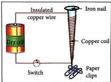
Fig 8.11: Experimental setup of a simple electromagnet
Fig 8.11: Experimental setup of a simple electromagnet
Practical Applications of Electromagnets
Electromagnets are highly versatile because their magnetic field can be turned on and off. Their major uses include:
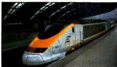
Fig 8.12: High-speed bullet train utilizing electromagnetic systems
Fig 8.12: High-speed bullet train utilizing electromagnetic systems

4. Practical Application: The Electric Bell
The electric bell is one of the most common and practical household applications of a temporary U-shaped electromagnet.
Construction
An electric bell consists of several components mounted on a flat wooden or plastic board:
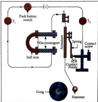
Fig 8.13: Detailed schematic of an electric bell circuit
Fig 8.13: Detailed schematic of an electric bell circuit
Step-by-Step Working Mechanism
5. Electromagnetic Induction and Faraday’s Laws
Electromagnetic Induction is the phenomenon of producing an electric current in a conductor due to a change in the magnetic lines of force (magnetic field) associated with that conductor. The current produced through this process is called induced current.
Faraday’s Experiment
Michael Faraday demonstrated electromagnetic induction using a multi-turn coil of insulated copper wire connected to a sensitive galvanometer (a device used to detect and measure very small electric currents).
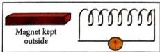
Fig 8.14: Magnet stationary outside coil (no current)
Fig 8.14: Magnet stationary outside coil (no current)
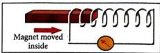
Fig 8.15: Magnet moving into the coil (current flows)
Fig 8.15: Magnet moving into the coil (current flows)
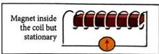
Fig 8.16: Magnet stationary inside the coil (no current)
Fig 8.16: Magnet stationary inside the coil (no current)
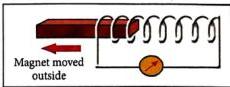
Fig 8.17: Magnet moving out of the coil (current flows in opposite direction)
Fig 8.17: Magnet moving out of the coil (current flows in opposite direction)
Experimental Observations
The Core Principle
The experiment works identically if the magnet is held stationary and the coil is moved. This proves that relative motion between the coil and the magnet is required to change the magnetic lines of force and induce an electric current.
Faraday’s Laws of Electromagnetic Induction
Based on his experimental observations, Faraday established two major laws:
Ways to Increase the Magnitude of Induced Current
To make the induced current stronger, you can:
6. Real-World Applications, Historical Impact, and Modern Science
Science and Scientists: Michael Faraday (1791–1867)
Michael Faraday was an English physicist and chemist widely considered one of the greatest experimentalists of all time.
Medical Applications of Electromagnetism: MRI vs." CT Scan
Electromagnetism plays an essential role in modern diagnostic medicine.
🌍 Eco-Soldier: Electromagnetic Fields and Human Well-Being
Many daily electronic devices—such as cell phones, laptops, and television screens—emit electromagnetic radiation.
Want to print your doc?
This is not the way.
This is not the way.

Try clicking the ··· in the right corner or using a keyboard shortcut (
CtrlP
) instead.