Skip to content
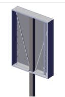
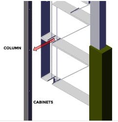
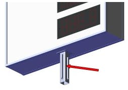
A pylon with the cabinets slid vertically onto the column before being secured in place.The column is not part of the column structure.The cabinets are built with an internal column pocket so the column can be secured to the cabinet structure. (The column pocket is not shown in the drawing to the left).A pylon with cabinets sliding horizontally onto the column, before being secured in place.It is important to note that the column can not be on the very edge of the cabinet. It should be inset as shown in the drawing to the left.Column slides into the cabinet’s cutout notch.A column that is part of the cabinet, that slides into the column below.The column is part of the cabinet structure, and extends out the of the bottom.The column extending out of the cabinet is often referred to as a stub column.The stub column sleeves into a larger main supporting column from grade.A steel plate, usually at the bottom of a cabinet that attaches to a matching plate at the top of the support column.The cabinet typically has an internal column to provide structural support.
Design Toolkit
- Pages
Share
Explore
 Pylon Cabinet Mounting Options
Last edited 1091 days ago by Adam Doll.
Sleeve Down
Sleeve On
Sleeve In
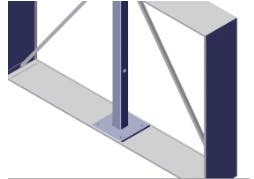
Mate Plate
Want to print your doc?
This is not the way.
This is not the way.

Try clicking the ··· in the right corner or using a keyboard shortcut (
CtrlP
) instead.