Skip to content
Design Toolkit
  • Pages
    • Design Toolkit Introduction
    • Meeting Agenda
    • Selkirk Drawing Stages
      • Drawing Stage One - Concept Art
      • Drawing Stage Two - Presentation Art
      • Drawing Stage Three - Initial Price Estimate
      • Drawing Stage Four - Firm Pricing and Corporate Client Drawings
      • Master Drawings
    • Selkirk Drawing Template
    • Selkirk Library Icons & Specifications
    • Drawing Standards
      • icon picker
        Fascia Signs
      • Channel Letters & Channel Shapes
      • Corporate Clients
      • Photo Overlays
      • Pylon Signs
      • Fuel Canopy
    • Materials
      • ACM / Aluminum Composite Material
      • Acrylic
      • Aluminum
      • Coroplast
      • Expanded PVC
      • Flex Face
      • MDO / Medium Density Overlay
      • Polycarbonate
      • Polystyrene
      • Steel Columns
    • Standard Size Guidelines
      • Channel Letters
      • Painting
      • Router Size Limitations
      • Shipping Guide
      • Thermal Forming / Molding
    • Selkirk Terminology
    • Sign Types
    • Pylon Sign Details
      • Pylon Types & Terminology
      • Pylon Base & Column Details
      • Pylon Cabinet Mounting Options
    • Cabinet & Fascia Details
      • Cabinet Types & Terminology
      • Single Sided Sign Cabinets
      • Double Sided Sign Cabinets
      • EX and SS Sign Extrusions
      • Single Face Illuminated Cabinet Standards
    • Channel Letter Details
      • Front-lit Channel Letter Materials
      • Front-lit Channel Letter Guidelines
      • Halo Lit Channel Letter Materials
      • Halo Lit Channel Letter Guidelines
      • Front and Halo Lit Channel Letter Materials
    • Routed Letter Details
    • Push Through & Routed Face Details
    • Preparing Files for Production
      • Production File Overview
      • Files for Digital Printing
      • Files for Vinyl Plotting
      • Files for CNC Router
      • File Resolution Guidelines
      • File Type Requirements
      • Raster vs. Vector
    • Minimum Survey Requirements
      • Face Replacements for Existing Frames
      • Frame Replacements for Existing Cabinets
      • New Inserts for Existing Two Column Pylon
      • New Columns for Existing Bases
      • New Cabinet for Existing Single Column Pylon
      • New Signage for Gas Canopy
      • Building Signage
      • Printable Quick Reference Guide for Minimum Survey Requirements
    • Signopedia

Fascia Signs

Last edited 1021 days ago by Adam Doll.

Illuminated Single Face Fascia Drawings

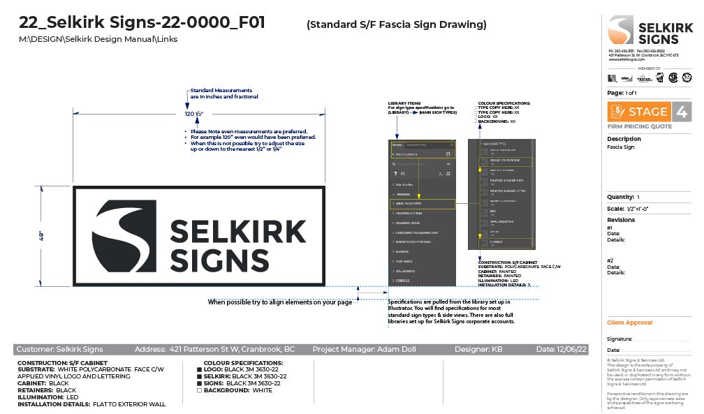
Drawings are dimensioned with measurements in fractional inches. Rounding should be set to 1/16”.
eg. 120 1/2” is the standard, rather than 120.5”.
A Creative Cloud library has been developed, with specification standards for each sign type.
These standards have been developed so that our drawings are a consistent, repeatable process. The screen shot below shows an example of the library item locations.
The construction specifications are placed to the left, below the grey information bar. Additional specifications are added in columns, working from left to right.
The grey bar can be moved up and down to accommodate the specifications.

Standar Fascia Sign Drawing.jpg
 
Want to print your doc?
This is not the way.
Try clicking the ⋯ next to your doc name or using a keyboard shortcut (
CtrlP
) instead.