Skip to content
Design Toolkit
  • Pages
    • Design Toolkit Introduction
    • Meeting Agenda
    • Selkirk Drawing Stages
      • Drawing Stage One - Concept Art
      • Drawing Stage Two - Presentation Art
      • Drawing Stage Three - Initial Price Estimate
      • Drawing Stage Four - Firm Pricing and Corporate Client Drawings
      • Master Drawings
    • Selkirk Drawing Template
    • Selkirk Library Icons & Specifications
    • Drawing Standards
      • Fascia Signs
      • Channel Letters & Channel Shapes
      • Corporate Clients
      • icon picker
        Photo Overlays
      • Pylon Signs
      • Fuel Canopy
    • Materials
      • ACM / Aluminum Composite Material
      • Acrylic
      • Aluminum
      • Coroplast
      • Expanded PVC
      • Flex Face
      • MDO / Medium Density Overlay
      • Polycarbonate
      • Polystyrene
      • Steel Columns
    • Standard Size Guidelines
      • Channel Letters
      • Painting
      • Router Size Limitations
      • Shipping Guide
      • Thermal Forming / Molding
    • Selkirk Terminology
    • Sign Types
    • Pylon Sign Details
      • Pylon Types & Terminology
      • Pylon Base & Column Details
      • Pylon Cabinet Mounting Options
    • Cabinet & Fascia Details
      • Cabinet Types & Terminology
      • Single Sided Sign Cabinets
      • Double Sided Sign Cabinets
      • EX and SS Sign Extrusions
      • Single Face Illuminated Cabinet Standards
    • Channel Letter Details
      • Front-lit Channel Letter Materials
      • Front-lit Channel Letter Guidelines
      • Halo Lit Channel Letter Materials
      • Halo Lit Channel Letter Guidelines
      • Front and Halo Lit Channel Letter Materials
    • Routed Letter Details
    • Push Through & Routed Face Details
    • Preparing Files for Production
      • Production File Overview
      • Files for Digital Printing
      • Files for Vinyl Plotting
      • Files for CNC Router
      • File Resolution Guidelines
      • File Type Requirements
      • Raster vs. Vector
    • Minimum Survey Requirements
      • Face Replacements for Existing Frames
      • Frame Replacements for Existing Cabinets
      • New Inserts for Existing Two Column Pylon
      • New Columns for Existing Bases
      • New Cabinet for Existing Single Column Pylon
      • New Signage for Gas Canopy
      • Building Signage
      • Printable Quick Reference Guide for Minimum Survey Requirements
    • Signopedia

Photo Overlays

Last edited 999 days ago by Adam Doll.
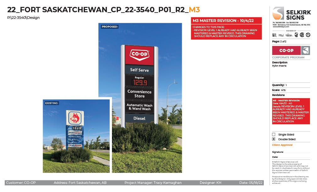
Photo overlays are used to show how the sign will look, using before and after photos. The example below shows the original Husky pylon sign, and the proposed render showing how it will look with the new CO-OP signage installed.
It is very important to show the scale of the sign to the photo as accurately as possible. In the case below, there is an existing sign so it is relatively easy if we have a few measurements. If there isn’t an existing sign, it can make accurate scaling difficult.
We often do initial drawings without a site survey. In these cases, adjustments should be done when the survey does come in to accurately reflect the survey sizes and proposed render.
22_FORT SASKATCHEWAN_CP_22-3540_P01_R2_M3 Photo Overlay.jpg
 
Want to print your doc?
This is not the way.
Try clicking the ⋯ next to your doc name or using a keyboard shortcut (
CtrlP
) instead.