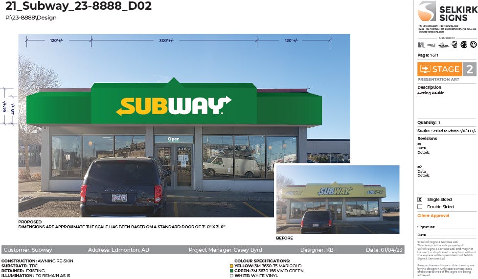
Skip to content
Design Toolkit
  • Pages
    • Design Toolkit Introduction
    • Meeting Agenda
    • Selkirk Drawing Stages
      • Drawing Stage One - Concept Art
      • icon picker
        Drawing Stage Two - Presentation Art
      • Drawing Stage Three - Initial Price Estimate
      • Drawing Stage Four - Firm Pricing and Corporate Client Drawings
      • Master Drawings
    • Selkirk Drawing Template
    • Selkirk Library Icons & Specifications
    • Drawing Standards
      • Fascia Signs
      • Channel Letters & Channel Shapes
      • Corporate Clients
      • Photo Overlays
      • Pylon Signs
      • Fuel Canopy
    • Materials
      • ACM / Aluminum Composite Material
      • Acrylic
      • Aluminum
      • Coroplast
      • Expanded PVC
      • Flex Face
      • MDO / Medium Density Overlay
      • Polycarbonate
      • Polystyrene
      • Steel Columns
    • Standard Size Guidelines
      • Channel Letters
      • Painting
      • Router Size Limitations
      • Shipping Guide
      • Thermal Forming / Molding
    • Selkirk Terminology
    • Sign Types
    • Pylon Sign Details
      • Pylon Types & Terminology
      • Pylon Base & Column Details
      • Pylon Cabinet Mounting Options
    • Cabinet & Fascia Details
      • Cabinet Types & Terminology
      • Single Sided Sign Cabinets
      • Double Sided Sign Cabinets
      • EX and SS Sign Extrusions
      • Single Face Illuminated Cabinet Standards
    • Channel Letter Details
      • Front-lit Channel Letter Materials
      • Front-lit Channel Letter Guidelines
      • Halo Lit Channel Letter Materials
      • Halo Lit Channel Letter Guidelines
      • Front and Halo Lit Channel Letter Materials
    • Routed Letter Details
    • Push Through & Routed Face Details
    • Preparing Files for Production
      • Production File Overview
      • Files for Digital Printing
      • Files for Vinyl Plotting
      • Files for CNC Router
      • File Resolution Guidelines
      • File Type Requirements
      • Raster vs. Vector
    • Minimum Survey Requirements
      • Face Replacements for Existing Frames
      • Frame Replacements for Existing Cabinets
      • New Inserts for Existing Two Column Pylon
      • New Columns for Existing Bases
      • New Cabinet for Existing Single Column Pylon
      • New Signage for Gas Canopy
      • Building Signage
      • Printable Quick Reference Guide for Minimum Survey Requirements
    • Signopedia

Drawing Stage Two - Presentation Art

Stage two drawings are not intended for pricing.
Last edited 1022 days ago by Adam Doll.

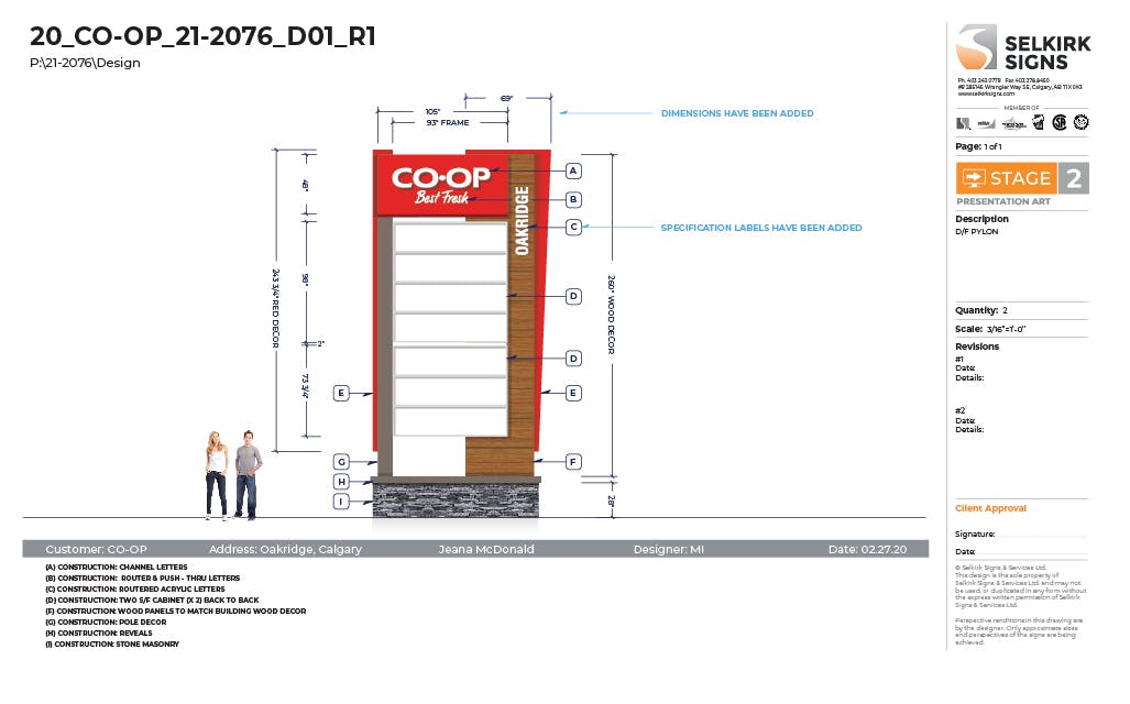
What is a stage two drawing?

Stage two drawings are intended to provide a little more detail than a stage one drawing, while still not requiring the designer to spend time working out build details for manufacturing purposes. For a design process like our example Calgary CO-OP pylon, some dimensions and basic specifications are added. The sign could be manufactured in various different ways, so we don’t go into specific details yet. For example, the CO-OP Best Fresh letters could be channel letters, routed and push-thru or even single face illuminated cabinets. Important considerations for sign type options are budget, size available, and desired appearance.
Stage 2.jpg

Stage two - Presentation photo overlays

Stage two drawings can also be presented as a photo overlay with or without scaled dimensions. This stage is quite flexible in terms of what is provided on the drawing. The reason for not including dimensions may be because we have no way to scale the building. However, typically we can scale a straight on photo using the doors, as they are commonly 7 feet tall by 3 feet wide.
Below is a good example of a stage two photo overlay drawing.
Before and after photos are provided.
Approximate dimensions and specifications have been included.
For this photo the scale has been based on a standard door size of 7’x3’.

Subway_21-2436_D02 Copy.jpg
 
Want to print your doc?
This is not the way.
Try clicking the ⋯ next to your doc name or using a keyboard shortcut (
CtrlP
) instead.