Skip to content
Design Toolkit
  • Pages
    • Design Toolkit Introduction
    • Meeting Agenda
    • Selkirk Drawing Stages
      • Drawing Stage One - Concept Art
      • Drawing Stage Two - Presentation Art
      • Drawing Stage Three - Initial Price Estimate
      • Drawing Stage Four - Firm Pricing and Corporate Client Drawings
      • Master Drawings
    • Selkirk Drawing Template
    • Selkirk Library Icons & Specifications
    • Drawing Standards
      • Fascia Signs
      • Channel Letters & Channel Shapes
      • Corporate Clients
      • Photo Overlays
      • Pylon Signs
      • icon picker
        Fuel Canopy
    • Materials
      • ACM / Aluminum Composite Material
      • Acrylic
      • Aluminum
      • Coroplast
      • Expanded PVC
      • Flex Face
      • MDO / Medium Density Overlay
      • Polycarbonate
      • Polystyrene
      • Steel Columns
    • Standard Size Guidelines
      • Channel Letters
      • Painting
      • Router Size Limitations
      • Shipping Guide
      • Thermal Forming / Molding
    • Selkirk Terminology
    • Sign Types
    • Pylon Sign Details
      • Pylon Types & Terminology
      • Pylon Base & Column Details
      • Pylon Cabinet Mounting Options
    • Cabinet & Fascia Details
      • Cabinet Types & Terminology
      • Single Sided Sign Cabinets
      • Double Sided Sign Cabinets
      • EX and SS Sign Extrusions
      • Single Face Illuminated Cabinet Standards
    • Channel Letter Details
      • Front-lit Channel Letter Materials
      • Front-lit Channel Letter Guidelines
      • Halo Lit Channel Letter Materials
      • Halo Lit Channel Letter Guidelines
      • Front and Halo Lit Channel Letter Materials
    • Routed Letter Details
    • Push Through & Routed Face Details
    • Preparing Files for Production
      • Production File Overview
      • Files for Digital Printing
      • Files for Vinyl Plotting
      • Files for CNC Router
      • File Resolution Guidelines
      • File Type Requirements
      • Raster vs. Vector
    • Minimum Survey Requirements
      • Face Replacements for Existing Frames
      • Frame Replacements for Existing Cabinets
      • New Inserts for Existing Two Column Pylon
      • New Columns for Existing Bases
      • New Cabinet for Existing Single Column Pylon
      • New Signage for Gas Canopy
      • Building Signage
      • Printable Quick Reference Guide for Minimum Survey Requirements
    • Signopedia
Share
Explore

Fuel Canopy

Last edited 999 days ago by Adam Doll.

Fuel Canopy Drawings

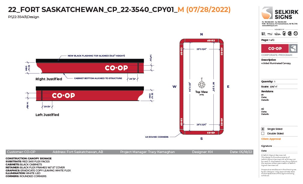
The example below show the typical standards to be followed for a CO-OP fuel canopy. Drawings for other clients are handled in a similar manner.
The measurements are given in feet and inches for fuel canopies. The longer measurements in inches can be hard to visualize. For example, 1085 ¼” vs 90’-5 ¼”. Feet and inches gives a much better idea of the size.
The library contains layouts and brand standards for all of Selkirk’s Corporate clients. These are to be used for a consistent and efficient workflow.
When setting up a drawing for new cabinets on a fuel canopy the most important survey measurements are of the actual structure.
22_FORT SASKATCHEWAN_CP_22-3540_CPY01_R1_M.jpg

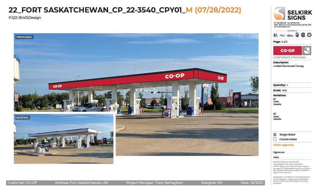
Fuel Canopy Photo Overlay Example

Fuel Canopy AdobeStock_461337338 SM.jpg

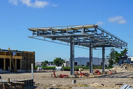
Photo showing a typical fuel canopy structure.

Plywood or metal backing is often added over top of the structure that is visible in this photo. The fuel canopy sign band is installed on top of the sheathing, tying into the structure behind.
Federated Co-op canopies include an additional layer of ⅜” thick DecoFoam on top of the sheathing.
22_FORT SASKATCHEWAN_CP_22-3540_CPY01_Photo Overlay.jpg

 
Want to print your doc?
This is not the way.
Try clicking the ⋯ next to your doc name or using a keyboard shortcut (
CtrlP
) instead.