Skip to content

This is our last chance to go over the drawing details and catch errors.Never assume that a drawing is correct and free of errors, this is the most important consideration to avoid mistakes.If there was a site survey, go back and review it.Does the survey still seem clear?Do the measurements add up?What previously seemed clear may not look quite as solid now that the job is moving to production. Ask more questions if required.Ensure the specifications are complete and as clear as possible.Check that all dimensions are accurate.Dimensions should be in inches. (There are a few exceptions to this rule, such as Federated CO-OP canopy drawings).If a colour match is required, it should be specified on the master. (There are some cases where tight manufacturing timelines require jobs to be mastered before a certain colour has been confirmed, usually building paint matches).The drawing should no longer have plus/minus or TBC on any of the dimensions.There should not be any details listed as TBC. Everything should be confirmed by now. (Again, there may be rare cases where the drawing needs to be mastered before some details can be confirmed).See THIS SECTION for a list of minimum survey requirements.
Design Toolkit
- Pages
Share
Explore
 Master Drawings
Production Drawings
Last edited 1134 days ago by Adam Doll.
What is a master drawing?
This is the final drawing that will be released to the production team. This should be the last time we work on the drawing, and it is our responsibility to double check all the details and look for any errors.
Considerations when mastering a drawing
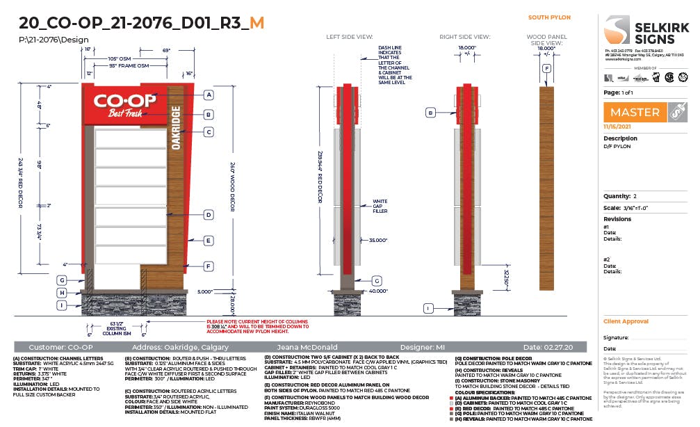
Below is an example of a mastered drawing. Everything has been double checked for accuracy and clarity. The depths on the side views have been added in this case because drafting was consulted before the drawing was submitted for master. Drafting will often have specific requirements and should be consulted if we are providing side views for a non-standard sign.
The orange “M” at the end of the drawing name, and the master stamp, are indicators that this drawing is a master. For a typical corporate drawing, the custom corporate icon would remain and the drawing name would be appended with an “M” and the master date. See THIS DRAWING for an example.
Want to print your doc?
This is not the way.
This is not the way.
Try clicking the ··· in the right corner or using a keyboard shortcut (
CtrlP
) instead.