Skip to content


Amonia
Total equipment of pabrik amonia 1a is with total detail equipment is items | items of detail equipment already build and there areitems need to be build in 3D model.
29
138
18
120
Total interaction in working interactions is that consist of interaction in startup scenarios, shutdown scenarios, and normal operation from Working instruction. The total number of interaction from operating window amonia 1a document is
3021
2077
932
12
209
A: 3 aset
Total Interactions : Interactions (startup + shutdown + normal operation)
3230
2077
932
221
Total Unique Equipment Items : items
120
Pabrik 1A Amonia
category
Proses
Equipment
Detail Equipment
3D Done ?
Asset Image
Kesulitan 2
Mandays
A
81
Frontend Process Ammonia
1.1 NG Compressor
NG KO Drum (V-0101)
1
1
Frontend Process Ammonia
1.1 NG Compressor
NG Compressor Suction Separator (V-0411)
2
2
Frontend Process Ammonia
1.1 NG Compressor
Fuel NG Preheater (E-0101)
2
2
Frontend Process Ammonia
1.1 NG Compressor
NG Recycle Cooler (E-0411)
2
2
Frontend Process Ammonia
1.2 Air Compressor
Air Compresssor First Intercooler (E-0421)
1
1
Frontend Process Ammonia
1.2 Air Compressor
Air Compresssor Second Intercooler (E-0422)
1
1
Frontend Process Ammonia
1.2 Air Compressor
Air Compresssor Third Intercooler (E-0423)
1
1
Frontend Process Ammonia
1.2 Air Compressor
Air Compressor First Separator (V-0421)
1
1
Frontend Process Ammonia
1.2 Air Compressor
Air Compressor Second Separator (V-0422)
1
1
Frontend Process Ammonia
1.2 Air Compressor
Air Compressor Third Separator (V-0423)
1
1
Frontend Process Ammonia
1.3 Desulphurizer
Air Compressor Dry Gas Seal System
1
1
Frontend Process Ammonia
1.3 Desulphurizer
Desul Temp in CV, TV-0209
1
1
Frontend Process Ammonia
1.4 Process Steam
Line steam to Gas + Control Valve FV-0204/6
2
2
Frontend Process Ammonia
1.6 Primary Reformer
ID Fan/Fuel Gas Blower (K-0201 A/B)
3
3
Frontend Process Ammonia
1.6 Primary Reformer
NG Fuel System (CV FV-0215/6 + Line to burner)
1
1
Frontend Process Ammonia
1.6 Primary Reformer
Fuel off gas System (CV FV-0214 + Line to burner)
2
2
Frontend Process Ammonia
1.6 Primary Reformer
Feed Gas & Steam Preheater (E-0201)
1
1
Frontend Process Ammonia
1.6 Primary Reformer
Process Air Preheater (E-0202 AB)
1
1
Frontend Process Ammonia
1.6 Primary Reformer
Steam Superheater (E-0203)
1
1
Frontend Process Ammonia
1.6 Primary Reformer
NG Preheater (E-0204 ABC)
1
1
Frontend Process Ammonia
1.6 Primary Reformer
Catalyst tube + lantai top tube
2
2
Frontend Process Ammonia
1.7 Process Air
Line + CV FV-0209/211/212
1
1
Frontend Process Ammonia
1.8 Secondary Reformer
Check valve udara to SR
1
1
Frontend Process Ammonia
1.9 Reformed Gas Waste Heat Boiler
E-0208
1
1
Frontend Process Ammonia
1.11 CG Steam Superheater (E-0209)
E-0209
1
1
Frontend Process Ammonia
1.12 Methanator Trim Heater (E-0211)
E-0211
2
2
Frontend Process Ammonia
1.13 BFW Preheater No. 1 (E-0212)
E-0212 A/B
2
2
Frontend Process Ammonia
1.16 Startup N2 Circulation System
N2 Blower (K-0203)
1
1
Frontend Process Ammonia
1.16 Startup N2 Circulation System
Start up N2 Cooler (E-0214)
1
1
Frontend Process Ammonia
1.16 Startup N2 Circulation System
Start up N2 separatot (V-0202)
1
1
Frontend Process Ammonia
1.16 Startup N2 Circulation System
Start up N2 Heater (E-0216)
1
1
Steam System
2.2 Chemical System Deaerator
Hydrazine Injection Z-2501
2
2
Steam System
2.2 Chemical System Deaerator
ammonia injection (Z-2502)
1
1
Steam System
2.3 BFW Pump
pump (P-2501 A dan P-2501 B)
3
3
Steam System
2.4 Steam Drum
HP Steam Drum V-0201
2
2
Steam System
2.4 Steam Drum
Blowdown Drum (V-0211)
2
2
Steam System
2.4 Steam Drum
Blowdown Cooler (E-1101)
1
1
Steam System
2.6 Turbine Condenser
E-0401 + E-0401 P1A/B
1
1
Middle End Process
3.1 CO2 Removal
MDEA Filter (F-0301)
2
1
Middle End Process
3.1 CO2 Removal
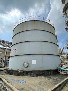
MDEA Solution Storage Tank (T-0301)
1
1
Middle End Process
3.1 CO2 Removal
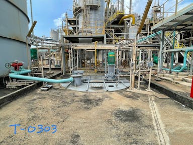
MDEA Solution Sump Tank (T-0303)
1
1
Middle End Process
3.1 CO2 Removal
CO2 product cooelr (E-0308)
1
1
Middle End Process
3.1 CO2 Removal
Solution Heat Exchanger (E-0301AB)
2
2
Middle End Process
3.1 CO2 Removal
Lean Solution Cooler (E-0303)
1
1
Middle End Process
3.1 CO2 Removal
DFW Preheater No. 1 (E-0304)
1
1
Middle End Process
3.1 CO2 Removal
DFW Preheater No. 2 (E-0305)
1
1
Middle End Process
3.1 CO2 Removal
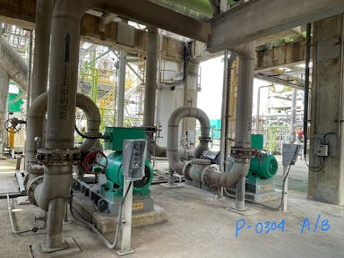
Overhead Condensate Pump (P-0304)
2
2
Middle End Process
3.1 CO2 Removal
Process Gas Separator (V-0304)
2
2
Middle End Process
3.1 CO2 Removal
MDEA Recycle Separator (V-0306)
1
1
Middle End Process
3.2 Process Condensate Treatment
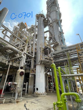
Process Condensate Stripper (C-0701)
2
2
Middle End Process
3.2 Process Condensate Treatment
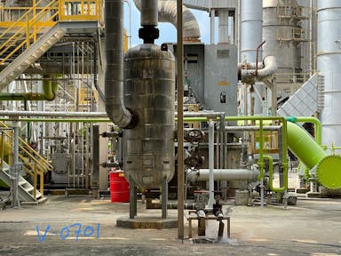
Process Condensate KO Drum (V-0701)
2
2
Middle End Process
3.2 Process Condensate Treatment
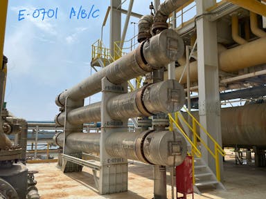
Process Condensate Exchanger (E-0701 ABC)
1
1
Middle End Process
3.2 Process Condensate Treatment
Stripped Condensate Cooler (E-0703)
1
1
Middle End Process
3.3 Methanator
Methanator (R-0301)
2
2
Middle End Process
3.3 Methanator
Methanator Heat Exchnager (E-0311)
2
2
Middle End Process
3.3 Methanator
Final Cooler (E-0312)
1
1
Middle End Process
3.3 Methanator
Final Gas Separator (V-0311)
1
1
Back End Process
4.1 Syngas Compressor
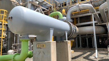
Syngas First Intercooler (E-0431)
1
1
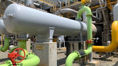
Back End Process
4.1 Syngas Compressor
Syngas Second Intercooler (E-0432)
1
1
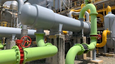
Back End Process
4.1 Syngas Compressor
Syngas Aftercooler (E-0433)
1
1
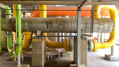
Back End Process
4.1 Syngas Compressor
Circulator Recycle Cooler (E-0434)
1
1
Back End Process
4.1 Syngas Compressor
Syngas Compressor First Separator (V-0431)
1
1
Back End Process
4.1 Syngas Compressor
Syngas Compressor Second Separator (V-0432)
1
1
Back End Process
4.1 Syngas Compressor
Syngas Compressor After Separator (V-0433)
1
1
Back End Process
4.2 Ammonia Synthesis Loop
Start Up Heater (H-0501)
2
2
Back End Process
4.2 Ammonia Synthesis Loop
Syngas Steam Superheater (E-0500)
1
1
Back End Process
4.2 Ammonia Synthesis Loop
SG Waste Heat Boiler (E-0501)
2
2
Back End Process
4.2 Ammonia Synthesis Loop
SG BFW Preheater (E-0502)
1
1
Back End Process
4.2 Ammonia Synthesis Loop
Water Cooler (E-0504)
1
1
Back End Process
4.2 Ammonia Synthesis Loop
First Cold Exchanger (E-0505)
2
2
Back End Process
4.2 Ammonia Synthesis Loop
First Ammonia Chiller (E-0506)
1
1
Back End Process
4.2 Ammonia Synthesis Loop
Second Cold Exchanger (E-0507)
1
1
Back End Process
4.2 Ammonia Synthesis Loop
Second Ammonia Chiller (E-0508)
1
1
Back End Process
4.2 Ammonia Synthesis Loop
PG Chiller (E-0514)
2
2
Back End Process
4.3 Refrigerant Compressor
Ammonia Intercooler (E-0441)
1
1
Back End Process
4.3 Refrigerant Compressor
Ammonia Compressor 2nd Stage KO Drum (V-0442)
1
1
Back End Process
4.3 Refrigerant Compressor
Ammonia Compressort 3rd Stage KO Drum (V-0443)
1
1
Back End Process
4.4 Refrigerant System
Ammonia Condenser (E-0510)
1
1
Back End Process
4.4 Refrigerant System
Inert Gas Chiller (E-0511)
1
1
Back End Process
4.4 Refrigerant System
Ammonia Product Heater (E-0512)
1
1
Back End Process
4.4 Refrigerant System
Ammonia Accumulator (V-0504)
1
1
81
Count
107
Sum
C
13
Frontend Process Ammonia
1.1 NG Compressor
NG Comp Lube Oil System (reservoir, pump, filter, cooler)
2
Frontend Process Ammonia
1.2 Air Compressor
Air Compresor turbine (TS-0421)
3
3
Frontend Process Ammonia
1.2 Air Compressor
Air Compressor Lube Oil System (reservoir, pump, filter, cooler)
3
3
Steam System
2.6 Turbine Condenser
E-2302 + E-2302 P1A/B
3
3
Middle End Process
3.1 CO2 Removal
Lube oil System P-0301A
3
3
Middle End Process
3.1 CO2 Removal
Lube oil System P-0301B
3
3
Middle End Process
3.1 CO2 Removal
Semilean Pump C (P-0301 C + motor)
3
3
Middle End Process
3.1 CO2 Removal
Lube oil System P-0301C
3
3
Middle End Process
3.1 CO2 Removal
MDEA Lean pump (P-0302 A dan B)
3
3
Middle End Process
3.1 CO2 Removal
Hydraulic turbine (TX-0301)
3
3
Back End Process
4.1 Syngas Compressor
Syngas Compressor Lube Oil System (reservoir, pump, cooler, filter)
3
3
Back End Process
4.1 Syngas Compressor
Syngas Compressor Dry Gas Seal System
3
3
Back End Process
4.3 Refrigerant Compressor
Refrigerant Compressor Dry Gas Seal System
3
3
13
Count
36
Sum
B
26
Frontend Process Ammonia
1.1 NG Compressor
NG Comp Dry Gas Seal System
3
3
Frontend Process Ammonia
1.2 Air Compressor
Air Compressor Suction Filter (F-0421)
1
1
Frontend Process Ammonia
1.2 Air Compressor
Air Compressor (K-0421)
1
1
Frontend Process Ammonia
1.5 Process Gas
CV FV-0201, 0201A, 0203
2
2
Frontend Process Ammonia
1.6 Primary Reformer
E-0205 BFW Preheater
2
2
Frontend Process Ammonia
1.15 BFW Preheater No. 2 (E-0213)
E-0213 A/B
2
2
Steam System
2.1 Deaerator
Deaerator Steam Stripping Line
2
2
Steam System
2.3 BFW Pump
turbine (TS-2501)
2
2
Steam System
2.5 Steam Header
Letdown HP to MP (line + CV : PV11021&2)
2
2
Steam System
2.5 Steam Header
MP Steam Vent (PV-11034&2)
2
2
Middle End Process
3.1 CO2 Removal
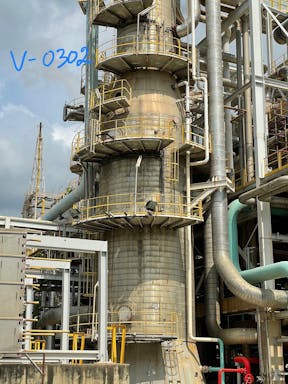
HP Flash Drum (V-0302)
3
3
Middle End Process
3.1 CO2 Removal
Semilean Pump A (P-0301 A + motor + TX)
2
2
Middle End Process
3.1 CO2 Removal
Semilean Pump B (P-0301 B + TS)
3
3
Middle End Process
3.1 CO2 Removal
Reboiler (E-0302)
2
2
Middle End Process
3.1 CO2 Removal
Split stream pump (P-0303 A/B))
3
3
Middle End Process
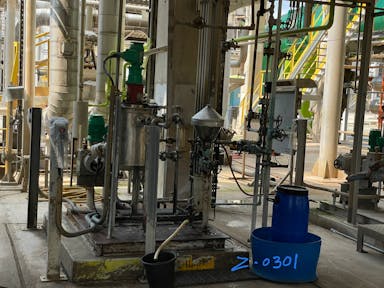
3.1 CO2 Removal
Antifoam Injection System (Z-0301)
2
2
Middle End Process
3.1 CO2 Removal
Solution Transfer Pump (P-0305)
2
2
Middle End Process
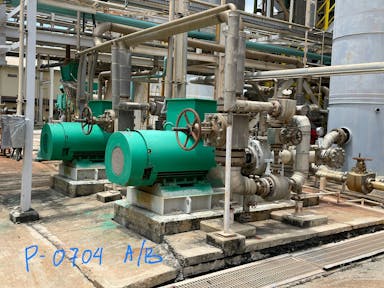
3.2 Process Condensate Treatment
Condensate Pump (P-0704 AB)
1
1
Back End Process
4.2 Ammonia Synthesis Loop
Hot Heat Exchanger (E-0503)
2
2
Back End Process
4.2 Ammonia Synthesis Loop
PG Separator (V-0514)
2
2
Back End Process
4.3 Refrigerant Compressor
Refrigerant Compressor (K-0441)
2
2
Back End Process
4.3 Refrigerant Compressor
Refrigerant Compressor Turbine (TS-0441)
2
2
Back End Process
4.4 Refrigerant System
Inert Gas Separator (V-0505)
2
2
Back End Process
4.4 Refrigerant System
Ammonia Product Pump (P-0501 A/B)
2
2
Back End Process
4.4 Refrigerant System
Let Down Vessel (V-0502)
2
2
Steam System
2.1 Deaerator
Deaerator (V-2501)
1
1
26
Count
52
Sum
120
Count
195
Sum
Total equipment
29
Total detail equipment | detail equipment yang sudah dimodelkan | detail equipment yang belum dimodelkan
138
18
120
3 ORANG
A: 81 → 1 orang 27 → 9 hari
B : 26 → 1 orang 8.5 item → 10 hari
C : 13 → 1 orang 4 item → 12 hari
Total : 31 hari
sep okt novemver → pertengahan oktober selesai
List Working Instructions 3
Nama Dokumen
Startup
Shutdown
Normal Operation
Total
WI-AM1A-SMT-OPS-05-007 (BFW SYSTEM _ FILL UP STEAM DRUM)
41
20
61
WI-AM1A-SMT-OPS-05-029 (AKTIFKAN STEAM SH SM SML SL HEADER)
99
20
119
WI-AM1A-SMT-OPS-05-030 (P-2501 AB BFW PUMP )
85
15
100
WI-AM1A-SMT-OPS-05-032 (AKTIFKAN GAS DARI SKG KE V - 0101)
30
0
30
WI-AM1A-SMT-OPS-05-033 (KM-0201 AB (ID FAN REFORMER)
18
17
35
WI-AM1A-SMT-OPS-05-034 (K-0203 (N2 BLOWER)
19
5
24
WI-AM1A-SMT-OPS-05-035 (AKTIFKAN FUEL SYSTEM REFORMER)
20
0
20
WI-AM1A-SMT-OPS-05-036 (AKTIFKAN NG COND RECOVERY KE FUEL SYSTEM)
19
0
19
WI-AM1A-SMT-OPS-05-037 (HEATING UP REFORMER _ HTS DGN SIRKULASI N2)
69
0
69
WI-AM1A-SMT-OPS-05-038 (IMPORT HYDROGEN DARI INTEGRASI)
15
0
15
WI-AM1A-SMT-OPS-05-039 (DESULPHURISER R-0201 _ R-0202)
12
0
12
WI-AM1A-SMT-OPS-05-040 (REFORMER)
112
0
112
WI-AM1A-SMT-OPS-05-041 (MASUKAN _ CABUT UDARA PROSES R-0203)
42
0
42
WI-AM1A-SMT-OPS-05-043 (AKTIFKAN _ NON AKTIFKAN LTS)
15
8
23
WI-AM1A-SMT-OPS-05-044 (PEMBUATAN DAN SIRKULASI MDEA)
48
0
48
WI-AM1A-SMT-OPS-05-045 (P 0302 AB (MDEA LEAN SOLUTION PUMP)
89
59
148
WI-AM1A-SMT-OPS-05-046 (P-0301 ABC (MDEA SEMI LEANSOLUTION PUMP)
236
35
271
WI-AM1A-SMT-OPS-05-047 (AKTIFKAN _ NON AKTIFKAN TX-0301)
18
6
24
WI-AM1A-SMT-OPS-05-049 (P-0303 AB (SPLIT STREAM PUMP)
37
9
46
WI-AM1A-SMT-OPS-05-050 (P-0304 AB (O.H CONDENSATE PUMP)
30
8
38
WI-AM1A-SMT-OPS-05-051 (PMP-0704 AB (PC PUMP)
35
9
44
WI-AM1A-SMT-OPS-05-052 (C-0701 PC STRIPER)
24
59
83
WI-AM1A-SMT-OPS-05-053 (EXTRA COOLER E-0308A)
9
0
9
WI-AM1A-SMT-OPS-05-054 (MASUKAN GAS KE CO2 REMOVAL)
34
0
34
WI-AM1A-SMT-OPS-05-055 (LOADING ANTIFOAM DI CO2 REMOVAL)
18
0
18
WI-AM1A-SMT-OPS-05-056 (F-0301 _ F-0302 (MDEA FILTER)
33
33
66
WI-AM1A-SMT-OPS-05-057 (EXPORT CO2 KE INTEGRASI)
13
0
13
WI-AM1A-SMT-OPS-05-059 (P-0308 (CONDENSATE RECOVERY PUMP)
25
0
25
WI-AM1A-SMT-OPS-05-060 (R-0301 (METHANATOR)
18
20
38
WI-AM1A-SMT-OPS-05-061 (TS K-0411 ( NG COMP)
77
0
77
WI-AM1A-SMT-OPS-05-062 (TSK-0421 (AIR COMP)
21
105
126
WI-AM1A-SMT-OPS-05-063 (TSK-0431 (SYN GAS COMP)
191
15
206
WI-AM1A-SMT-OPS-05-064 (TSK-0441 (REFRIGERANT COMP)
150
20
170
WI-AM1A-SMT-OPS-05-065 (E-0401-P1 AB (CONDENSATE PUMP)
15
0
15
WI-AM1A-SMT-OPS-05-066 (K-0421-P1 AB (LUBE OIL PUMP)
60
0
60
WI-AM1A-SMT-OPS-05-067 (SWITCHING K-0421-E1 AB)
25
0
25
WI-AM1A-SMT-OPS-05-074 (REDUKSI, START _ SHUTDOWN R-0501)
106
25
131
WI-AM1A-SMT-OPS-05-076 (AKTIFKAN STEAM SUPERHEATER E-0500)
18
0
18
WI-AM1A-SMT-OPS-05-078 (P-0501 AB (NH3 PUMP)
70
0
70
WI-AM1A-SMT-OPS-05-081 (REFRIGERANT SYSTEM)
18
0
18
WI-AM1A-SMT-OPS-05-094 (SUPLAI GAS FAILURE)
63
0
63
WI-AM1A-SMT-OPS-05-095 ( I-81 AKTIF (ARU INTERNAL TRIP)
0
16
16
WI-AM1A-SMT-OPS-05-096 ( IS-51 AKTIF (SYNLOOP INTERNAL TRIP)
0
28
28
WI-AM1A-SMT-OPS-05-097 ( IS-44 AKTIF (K-0431 TRIP)
0
50
50
WI-AM1A-SMT-OPS-05-098 ( IS-45 AKTIF (K-0441 TRIP)
0
34
34
WI-AM1A-SMT-OPS-05-099 ( IS-33 AKTIF (METHANATOR R-0301 TRIP)
0
37
37
WI-AM1A-SMT-OPS-05-100 ( IS-42 AKTIF (K-0421 TRIP)
0
66
66
WI-AM1A-SMT-OPS-05-101 (IS-41 AKTIF (K-0411 TRIP)
0
71
71
WI-AM1A-SMT-OPS-05-102 (IS-31 AKTIF (MDEA PUMP TRIP)
0
43
43
WI-AM1A-SMT-OPS-05-103 (IS-32 AKTIF (CO2 REMOVAL INTERNAL TRIP)
0
44
44
WI-AM1A-SMT-OPS-05-104 (TRIP POMPA BFW P-2501 AB (I-251-1 AB)
0
55
55
There are no rows in this table
2077
Sum
932
Sum
12
Sum
3021
Sum
Total interaction in working interactions is that consist of interaction in startup scenarios, shutdown scenarios, and normal operation
3021
2077
932
12
Operating Window Amonia 1A
Tag No
P & ID
Description
Unit
Low Normal R III
High Normal R III
L (Alarm)
LL (TRIP)
H (ALARM)
HH (TRIP)
Low
High
LC-0101
P1
NG KO Drum Level
%
10
20
5
-
25
-
-
-
PAL-0102
P1
NG KO Drum Outlet
kg/cm²G
23
26
19
15
33
PC-0201
P1
Sulphur Adsorber ( R-0202 ) Outlet NG
kg/cm²G
41,5
42,5
35
-
43,5
46,5
AI-02062
P1
Sulphur Outlet R-0202
ppb
0
50
FC-0201
P2
Feed Gas & Steam Preheater ( E-0201 ) Inlet NG
Nm³/hr
48800
54000
41000
56000
FAL-0201
P2
Feed Gas & Steam Preheater ( E-0201 ) Inlet NG
Nm³/hr
48800
54000
41000
21000
FFI-0201
P2
E-0201 Gas / Air Ratio
Nm³/hr
0,63
0,65
0,58
0,51
FFI-0202
P2
E-0201 Gas / Air Ratio
Nm³/hr
0,63
0,65
0,58
0,51
FC-0204
P2
Feed Gas & Steam Preheater ( E-0201 ) Inlet NG
TPH
132
135
85
FFI-0204
P2
E-0201 Steam / Gas Ratio
kg/cm²G
2,59
2,79
2,1
FAL-0205
P2
Feed Gas & Steam Preheater ( E-0201 )Inlet NG
TPH
132
135
85
63,3
FFI-0205
P2
E-0201 Steam Gas / Air Ratio
kg/cm²G
2,59
2,79
2,1
1,81
FC-0206
P2
E-0201 Inlet SM Bypass
TPH
40
40
36
FC-0207
P2
Feed Gas & Steam Preheater
( E-0201 )Inlet NG
Nm³/hr
2960
2500
FC-0209
P2
PA Preheater - B E-0202 B inlet PA
Nm³/hr
76870
77000
65000
FAL-0210
P2
PA Preheater - B E-0202 B inlet PA
Nm³/hr
76870
77000
65000
38000
PAL-0203
P3
Primary Reformer ( H-0201 ) Inlet FG
kg/cm²G
2,5
2,8
0,1
7
PAH-0205
P3
Primary Reformer ( H-0201 )
mmH2O
-5
-3
3
PC-0206
P3
Primary Reformer ( H-0201 )
mmH2O
-5
-3
-15
0
PC-0212
P3
Primary Reformer ( H-0201 ) Inlet FG
kg/cm²G
5
5
4
6
7
PC-0218
P3
Primary Reformer ( H-0201 ) Inlet Off Gas
kg/cm²G
1,2
1,4
0,2
6,5
7
TI-0208
P2
Steam Preheater ( E-0201 ) Outlet NG
°C
535
535
545
TC-0209
P2
NG Preheater ( E-0204 A ) Outlet NG
°C
400
400
380
420
425
TI-0210
P2
Proces Air Preheater ( E-0202 A ) Outlet PA
°C
540
550
570
580
TC-0212
P2
Steam Superheter ( E-0203 ) Outlet SH
°C
515
517
505
525
530
TI-0252
P3
Primary Reformer ( H-0201 )
°C
970
985
1060
TI-0253
P3
Primary Reformer ( H-0201 )
°C
970
985
1060
TI-0254
P3
Primary Reformer ( H-0201 )
°C
970
985
1060
TI-0255
P3
Primary Reformer ( H-0201 )
°C
760
794
804
Tubes Skin Temperature
°C
888
LC-0201
P4
Steam Drum ( V-0201 ) Level
%
40
50
30
70
LAL-0203
P4
Steam Drum ( V-0201 ) Level
%
40
50
30
10
-
PI-0210
P4
Steam Drum ( V-0201 ) Level
kg/cm²G
116
120
125
133,5
AI-0202
P4
Steam Drum ( V-0201 ) Outlet BD
8,8
9,5
8,5
10
AI-0203
P4
Steam Drum ( V-0201 ) Outlet BD
µs/cm
3
10
Chloride
ppm
3
PH
9,4
9,6
Eliminox
ppb
100
150
Hydrazine
ppb
7
Conductivity
µs/cm
10
LC-0205
P4
Blowdown Drum ( V-0211 ) Level
%
40
50
18,3
51,7
LAH-0221
U3
Start Up N2 Separator ( V-0202 ) Level
%
0
0
75
TI-0257
U3
Start Up N2 Separator ( V-0202 ) Outlet N2
°C
40
50
60
65
-
65
PD-0222
U3
Start Up N2 Blower ( K-0203 ) Suction N2
kg/cm²G
0,8
1
1,1
1,4
TI-0222
P4
RG WHB ( E-028 ) Inlet RG
°C
950
960
612
1000
TAH-0223
P4
RG WHB ( E-028 ) Inlet RG
°C
950
960
612
1000
1010
TC-0224
P4
RG WHB ( E-028 ) Outlet RG
°C
340
350
320
360
410
TI-0232
P5
HT CO Converter ( R-0204 ) Outlet RG
°C
417
417
450
470
TI-0234
P5
CG Steam Superheater ( E-0209 ) Outlet SH
°C
380
380
400
410
TC-0239
P5
BFW Preheater -B ( E-0212-B ) Outlet CG
°C
194
196
170
210
250
TI-0250
P5
LT CO Converter ( R-0205 ) Outlet CG
°C
211
211
185
235
250
PC-0213
P6
BFW Preheater No. 2 ( E-0213A ) Inlet CG
kg/cm²G
32,7
32,7
35,5
37,5
TI-0256
P6
BFW Preheater No. 2 ( E-0213A ) Inlet CG
°C
177
183
165
220
FC-0301
P7A
OH Condensate Pump A/B ( P-0304 A/B ) Discharge MAS
TPH
580
650
500
300
LC-0304
P7A
LP Flash Drum ( V-0301 ) Level
%
35
40
32,8
83,8
LAL-0305
P7A
LP Flash Drum ( V-0301 ) Level
%
35
40
5
LI-0306
P7A
LP Flash Drum ( V-0301 ) Level
%
35
40
5,6
87,7
TI-0305
P7A
LP Flash Drum ( V-0301 ) Outlet CO2
°C
40
43
45
60
FC-0302
P7A
Solution Heat Exchanger-B ( E-0301B ) Inlet MAS
TPH
480
510
345
230
LC-0302
P7A
CO2 Stripper ( C-0301 ) Level
%
60
60
38,9
61,1
LAH-0303
P7A
CO2 Stripper ( C-0301 ) Level
%
60
60
38,9
5,6
61,1
94,4
FI-0303
P7A
BFW Preheater No. 1 ( E-0304 ) Inlet BFW
TPH
330
340
140
120
FC-0304
P9
CO2 Absorber ( C-0302 ) inlet MAS
TPH
427
450
320
220
FC-0306
P9
CO2 Absorber ( C-0302 ) inlet MAS
TPH
2713
2850
2035
1350
LC-0310
P9
CO2 Absorber ( C-0302 ) Level
%
50
65
38,9
63
LAL-0311
P9
CO2 Absorber ( C-0302 ) Level
%
50
65
38,9
5
AI-0301
P9
CO2 Absorber ( C-0302 ) Outlet CG
% Vol
0,05
55
0,06
LC-0301
P9
Process Gas Separator ( V-0304 ) Level
%
50
60
41,7
8,3
64,6
LC-0307
P7B
HP Flash Drum ( V-0302 ) Level
%
40
45
37,5
61,5
LAH-0308
P7B
HP Flash Drum ( V-0302 ) Level
%
40
45
37,5
61,5
80
LC-0309
P7B
MDEA Recycle Separator ( V-0306 ) Level
%
40
45
22
74
92
PC-0306
P7B
MDEA Recycle Separator ( V-0306 )
kg/cm²G
7
8
9
12
TI-0324
P7B
MDEA Recycle Separator
( V-0306 ) Outlet HG
°C
30
40
45
LC-0312
P10
Final Gas Separator ( V-0311 ) Level
%
40
45
18,3
68,3
LAH-0313
P10
Final Gas Separator ( V-0311 ) Level
%
40
45
68,3
50
LI-0321
U4
MDEA Solution Sump Tank ( T-0303 ) Level
%
20
70
20,8
62,5
66,7
LI-0322
U4
MDEA Solution Storage Tank ( T-0303 ) Level
%
0
80
91,8
PAL-0307
P8
Hydraulic Turbine for P-0301-A Suction MAS
kg/cm²G
30,8
30,3
35,5
PAL-0308A
P8
Semi Lean Solution Pump A P-0301A Suction MAS
kg/cm²G
3,5
4,6
2,8
-0,5
8
PAL-0308B
P8
Semi Lean Solution Pump B P-0301B Suction MAS
kg/cm²G
3,5
4,6
2,8
-0,5
8
PAL-0308C
P8
Semi Lean Solution Pump C P-0301C Suction MAS
kg/cm²G
3,5
4,6
2,8
-0,5
8
PAL-0310A
P8
Lean Solution Pump A ( P-0302A ) Suction MAS
kg/cm²G
1,7
1,7
1
-0,5
8
PAL-0310B
P8
Lean Solution Pump B ( P-0302B ) Suction MAS
kg/cm²G
1,7
1,7
1
-0,5
8
PAL-0309A
P8
Split Steam Pump A ( P-0303A ) Suction MAS
kg/cm²G
3,5
4,7
2,8
-0,5
8
PAL-0309B
P8
Split Steam Pump B ( P-0303B ) Suction MAS
kg/cm²G
3,5
4,7
2,8
-0,5
8
PAL-0311
P8
P-0301 A/B/C & P-0303 A/B Seal Water
kg/cm²G
12
11,5
PC-0322
P8
P-0301 A/B/C & P-0303 A/B Seal Water
kg/cm²G
12
11,5
11
TC-0313
P10
Methanator ( R-0301 ) Inlet CG
°C
275
290
250
310
470
TI-0314
P10
Methanator ( R-0301 )
°C
290
290
310
TA-0315
P10
Methanator ( R-0301 )
°C
290
290
250
430
TI-0316
P10
Methanator ( R-0301 )
°C
300
300
320
TA-0317
P10
Methanator ( R-0301 )
°C
308
308
270
330
450
450
LI-0401
C1
NG Compressor Suction ( V-0411 ) Level
%
0
LAH-0421
C2
PA Compressor 1st ( V-0421 ) Level
%
0
50
LAH-0422
C2
PA Compressor 1st ( V-0421 ) Level
%
0
50
75
LAH-0423
C2
PA Compressor 2nd ( V-0422 ) Level
%
0
50
LAH-0424
C2
PA Compressor 2nd ( V-0422 ) Level
%
0
50
75
LAH-0425
C2
PA Compressor 3st ( V-0423 ) Level
%
0
50
LAH-0426
C2
PA Compressor 3st ( V-0423 ) Level
%
0
50
66,7
LC-0441
C3
SG Compressor 1st Separator ( V-0431 ) Level
%
0
2,5
77,5
LAH-0442
C3
SG Compressor 1st Separator ( V-0431 ) Level
%
0
77,5
90
LIC-0443
C3
SG Compressor 2nd Separator ( V-0432 ) Level
%
0
25
50
LAH-0444
C3
SG Compressor 2nd Separator ( V-0432 ) Level
%
0
50
75
LC-0445
C3
SG Compressor 3rd Separator ( V-0433 ) Level
%
0
25
75
LI-0481
C4
NH3 Compressor 2nd Stage KO Drum ( V-0442 )
%
0
51,7
LAH-0482
C4
NH3 Compressor 2nd Stage KO Drum ( V-0442 )
%
0
51,7
85
LIC-0483
C4
NH3 Compressor 3rd Stage KO Drum ( V-0443 )
%
0
20
50
LAH-0484
C4
NH3 Compressor 3rd Stage KO Drum ( V-0443 )
%
0
20
62,5
TI-0402
C1
NG Booster Compressor ( K-0411 ) Discharge NG
°C
65
115
180
TAH-0403
C1
NG Booster Compressor ( K-0411 ) Discharge NG
°C
104
4
115
180
180
ZAH-04102
C1
NG Booster Compressor ( K-0411 ) Thrust Position ( Vibrastion )
mm
-0,2
0,2
-0,6
0,6
0,8
XAH-04103 /
04104
C1
NG Booster Compressor ( K-0411 ) Journal Vibrastion
µm
< 42
42
78
TAH-04108 -
04111
C1
NG Booster Compressor ( K-0411 ) Journal Bearing Temperature
°C
< 110
110
TAH-04112
- 04114
C1
NG Booster Compressor ( K-0411 ) Thrust Bearing Temperature
°C
< 110
110
PI-0421
C2
PA Compressor ( K-0421 ) 1st Suction PA
kg/cm²G
-5
-15
1,8
TI-0421
C2
PA Compressor ( K-0421 )
1st Discharge PA
°C
195
195
205
220
TAH-0422
C2
PA Compressor ( K-0421 )
1st Discharge PA
°C
195
195
8
205
220
220
TI-0423
C2
PA Compressor ( K-0421 )
2nd Discharge PA
°C
210
215
225
230
TAH-0424
C2
PA Compressor ( K-0421 )
2nd Discharge PA
°C
210
215
8
225
230
230
TI-0425
C2
PA Compressor ( K-0421 )
3rd Discharge PA
°C
130
139
150
160
TAH-0426
C2
PA Compressor ( K-0421 )
3rd Discharge PA
°C
130
139
4
150
160
160
TI-0427
C2
PA Compressor ( K-0421 )
4th Discharge PA
°C
145
184
195
200
ZAH-04202
C1
PA Compressor ( K-0421 )
Thrust Position Vibration
mm
-0,2
0,2
-0,6
0,6
0,8
XAH 04203 /
04204
C1
PA Compressor ( K-0421 )
Journal Vibration
µm
< 55
55
104
TAH 04208 -
04211
C1
PA Compressor ( K-0421 )
Journal Bearing Temperature
°C
< 110
110
TAH 04213 -
04215
C1
PA Compressor ( K-0421 )
Thrust Bearing Temperature
°C
< 110
110
ZAH-04203
C1
PA Compressor ( K-0421 )
Thrust Position Vibration
mm
-0,2
0,2
0,6
0,8
XAH 04205 /
04206
C1
PA Compressor ( K-0421 )
Journal Vibration
µm
< 55
55
104
TAH 04209 /
04212
C1
PA Compressor ( K-0421 )
Journal Bearing Temperature
°C
< 110
110
TAH 04213 -
04215
C1
PA Compressor ( K-0421 )
Thrust Bearing Temperature
°C
< 110
110
PC-0441
C3
SG Compressor ( K-0431 )
1st Suction
kg/cm²G
29
29
28
39
TI-0442
C3
SG Compressor ( K-0431 )
1st Discharge SG
°C
95
98
110
120
TI-0443
C3
SG Compressor ( K-0431 )
2nd Discharge SG
°C
95
98
110
130
114
TALH
C3
SG Compressor ( K-0431 )
2nd Discharge SG
°C
95
98
4
110
130
114
TI-0445
C3
SG Compressor ( K-0431 )
Recycle Discharge SG
°C
40
44
50
60
TI-0446
C3
SG Compressor ( K-0431 )
3rd Discharge SG
°C
119
124
145
150
TALH-0447
C3
SG Compressor ( K-0431 )
3rd Discharge SG
°C
119
124
4
145
150
150
ZAH-04401
C3
SG Compressor ( K-0431 )
Thrust Position ( Vibration )
mm
-0,2
0,2
-0,75
0,75
0,8
XAH-04401 /
04202
C3
SG Compressor ( K-0431 )
Journal Vibration
µm
-
< 40.5
40,5
62,4
TAH -04405 -
04408
C3
SG Compressor ( K-0431 )
Journal Bearing Temperature
°C
< 120
120
TAH-04402 -
04404
C3
SG Compressor ( K-0431 )
Thrust Bearing Temperature
°C
< 120
120
ZAH-04203
C3
SG Compressor ( K-0431 )
Thrust Position ( Vibration )
mm
-0,2
0,2
-
-
0,6
0,8
ZAH-04201 /
04206
C3
SG Compressor ( K-0431 )
Journal Vibration
µm
< 55
55
104
TAH-04209 -
04212
C3
SG Compressor ( K-0431 )
Journal Bearing Temperature
°C
< 110
110
TAH-04213 -
04215
C3
SG Compressor ( K-0431 )
Thrust Bearing Temperature
°C
< 110
110
PI-0481
C4
NH3 Compressor ( K-0441 )
1st Suction AG
kg/cm²G
0
-0,02
20
TI-0483
C4
NH3 Compressor ( K-0441 )
2nd Suction AG
°C
80
87
100
110
TALH-0484
C4
NH3 Compressor ( K-0441 )
2nd Suction AG
°C
80
87
4
100
110
110
TI-0486
C4
NH3 Compressor ( K-0441 )
3rd Suction AG
°C
90
108
120
125
TALH-0487
C4
NH3 Compressor ( K-0441 )
3rd Suction AG
°C
90
108
4
120
125
125
ZAH-04802
C4
NH3 Compressor ( K-0441 )
Thrust Position ( Vibration )
mm
-0,5
0,5
-0,75
0,75
0,8
XAH-04803 -
04804
C4
NH3 Compressor ( K-0441 )
Journal Vibration
µm
< 40.5
40,5
62,4
TAH-04808 -
04811
C4
NH3 Compressor ( K-0441 )
Journal Bearing Temperature
°C
< 120
120
TAH-04812 -
04814
C4
NH3 Compressor ( K-0441 )
Thrust Bearing Temperature
°C
< 120
120
ZAH-04803
C4
NH3 Compressor ( K-0441 )
Thrust Position ( Vibration
mm
-0,5
0,5
-0,75
0,75
0,8
XAH-04805 -
04806
C4
NH3 Compressor ( K-0441 )
Journal Vibration
µm
< 40.5
40,5
62,4
TAH-04815 -
04818
C4
NH3 Compressor ( K-0441 )
Journal Bearing Temperature
°C
< 120
120
TAH-04819 -
04821
C4
NH3 Compressor ( K-0441 )
Thrust Bearing Temperature
°C
< 120
120
LIC-0501
P12
1st Chiller ( E-0506 ) Level
%
65
65
61,1
77,8
LIC-0502
P12
Inert Gas Chiller ( E-0511 ) Level
%
60
65
44
64
LIC-0504
P13
Purge Gas Chiller ( E-0514 ) Level
%
60
65
54
70
LIC-0505
P13
2nd Chiller ( E-0508 ) Level
%
65
65
61,1
77,8
LIC-0506
P13
NH3 Separator ( V-0501 ) Level
%
50
50
31
69
LAH-0507
P13
NH3 Separator ( V-0501 ) Level
%
50
50
31
69
70
LIC-0508
P14
Let Down Vessel ( V-0502 ) Level
%
20
25
54,7
85
LAL-0509
P14
Let Down Vessel ( V-0502 ) Level
%
20
25
< 20
LIC-0510
P14
Flash Vessel ( V-0503 ) Level
%
50
60
37,5
62,5
LAH-0511
P14
Flash Vessel ( V-0503 ) Level
%
55
60
37,5
6,8
62,5
93,2
LIC-0512
P15
Inert Gas Separator ( V-0505 ) Level
%
45
50
31
61
LIC-0513
P15
NH3 Accumulator ( V-0504 ) Level
%
35
40
17,8
82,1
PIC-0501
P11
Start Up Heater ( H-0501 ) Inlet FG
kg/cm²G
1,5
0,1
1,7
PALH-0502
P11
Start Up Heater ( H-0501 ) Inlet FG
kg/cm²G
1,5
0,1
0,05
1,7
2
PDI-0503
P11
1st NH3 Converter ( R-0501 ) Inlet SG
kg/cm²G
0,2
0,1
PDAL-0504
P11
1st NH3 Converter ( R-0501 ) Inlet SG
kg/cm²G
0,2
0,05
PIC-0507
P13
2nd Chiller ( E-0508 )
kg/cm²G
1,86
2,1
1,6
2,6
20
PIC-0508
P14
Let Down Vessel ( V-0502 )
kg/cm²G
25
22,5
27,5
27,5
PI-0511
P15
NH3 Accumulator ( V-0504 )
kg/cm²G
15,8
18,2
20
PIC-0516
P14
Flash Vessel ( V-0503 )
kg/cm²G
mmH2o
0.05
( 500 )
0.01
( 100 )
0.09
( 900 )
20
PAHH-0517
P14
Flash Vessel ( V-0503 )
kg/cm²G
0.05
( 500 )
0.01
( 100 )
0.09
( 900 )
1
20
TI-0501
P11
Start Up Heater ( H-0501 )
°C
833
880
900
TIC-0514
P11
1st NH3 Converter ( R-0501 )
°C
360
362
340
380
450
TI-0522
P11
1st NH3 Converter ( R-0501 ) Outlet SG
°C
439
460
470
TIC-0523
P11
SG Steam Superheater ( E-0500 )
Outlet SG
°C
376
360
400
450
TI-0536
P11
2nd NH3 Converter ( R-0502 )
Outlet SG
°C
418
440
470
TI-0539
P11
Hot Heat Exchanger ( E-0503 ) Inlet SG
°C
274
281
300
300
TIC-0542
P11
Hot Heat Exchanger ( E-0503 ) Outlet SG
°C
236
248
230
265
355
TI-0544
P11
SG BFW Preheater ( E-0502 ) Outlet BFW
°C
304
325
340
TIC-0560
P15
NH3 Product Heater-A ( E-0512A )
Outlet AL
°C
25
15
35
60
TI-0562
P11
Start Up Heater ( H-0501 ) Outlet SG
°C
510
520
PI-0448
U32
Steam Turbine for K-0431
( TS-0431 ) Outlet
kg/cm²G
43
44
TI-0429
U31
Steam Turbine for K-0421
( TS-021 ) Outlet
°C
55
60
TI-0449
U32
Steam Turbine for K-0431
( TS-0431 ) Outlet
°C
54,9
60
LIC-0701
U2
Process Condensate Stripper
( C-0701 ) Level
%
40
50
39,1
6,2
60,9
93,8
LI-0702
U2
Process Condensate KO Drum
( C-0701 ) Level
%
0
80
90
PI-0701
U2
Process Condensate Stripper
( C-0701 ) Outlet SM
kg/cm²G
39
40,4
38,5
42,5
46
TI-0701
U2
Process Condensate Stripper
( C-0701 ) Outlet SM
°C
245
250
260
410
AI-0701
U2
Process Condensate Cooler
( E-0703 ) Outlet CP
µs/cm
10
30
PA-1116-1
U10
Turbine Bypass Valve
( PV-1102-1 ) Supply Air
kg/cm²G
7
2
PA-1116-2
U10
Turbine Bypass Valve
( PV-1102-2 ) Supply Air
kg/cm²G
7
2
TI-1102
U10
HP Steam Header
°C
510
515
500
530
TI-1104
U10
Medium Steam Header
°C
384
387
375
410
TI-1105
U10
Medium Low Steam Header
°C
249
249
230
270
TI-1106
U10
Low Steam Header
°C
217
226
205
280
LIC-2501
U1
Deaerator ( V-2501 ) Level
%
65
70
60
75
LALH-2502
U1
Deaerator ( V-2501 ) Level
%
65
70
60
8,3
75
87,5
PIC-2501
U1
Deaerator ( V-2501 )
kg/cm²G
1,5
1,5
2
4
PA-2502A/B
U1
BFW Pump A/B
( P-2501A/B ) Suction BFW
kg/cm²G
3
2,6
6
PI-2503
U1
BFW Pump A/B
( P-2501A/B ) Discharge BFW
kg/cm²G
130
130
125
123
170
LI-2901
U19
MDEA Collection Sump Tank ( T-0304 )
%
20
80
35,7
21,4
78,6
92,9
There are no rows in this table
209
Count
Want to print your doc?
This is not the way.
This is not the way.

Try clicking the ··· in the right corner or using a keyboard shortcut (
CtrlP
) instead.