Skip to content
Oxygen Trauma: an appropriate blend of oxygen and outside air must be set to adequately and appropriately oxygenate the bloodVolume Trauma: the correct volume of air must be delivered to the lungs within a small range of precision to avoid exceeding the lung's intrinsic capacity (which can and does change rapidly throughout COVID-19's progression)Pressure Trauma: the delivered breaths must not exceed some pressure, determined by the lung's current compliance, which can damage the lung, so the speed of delivered inhalations must be finely adjustablePneumothorax (collapse of the lung): positive end-expiratory pressure (PEEP) must be maintained as to avoid the collapse of the lung's alveoli
 Control System
Consultations and Dangers
Traditional ventilators are extremely complex, intelligent, and expensive machines. We consulted with the anesthesiologist leading New York Presbyterian's ventilation strategy during the COVID-19 crisis as well as several other doctors to determine the minimum required sensing and control capabilities of an interim manual ventilation device to be considered clinically viable. In this process, we learned that COVID-19 causes a number of issues, even for traditional ventilators.
As the most basic start point, our ventilator must be controlled adequately to avoid the four basic causes of lung trauma:
Our design is able to avoid these dangers with fine control of the three aforementioned flow profile parameters: breaths per minute (BPM), tidal volume (TV), and inspiration to expiration ratio (I:E) in combination with the Ambu-bag's inbuilt PEEP valve.
Parameter Mapping
Though we can and have made rough calculations about the translation between the physical control of our mechanism and the parameters clinicians will set, such as the relation between compression depth and tidal volume for a given Ambu-bag size, precise correlation will need to be determined through rigorous testing.
Sensing
The medical professionals we spoke with told us that our device would minimally need to be able to measure Peak Inspiratory Pressure (PIP) and PEEP. The only reliable way to measure these and other respiratory metrics is through a direct pressure transducer connected to the airline between the ventilator and the patient. This is detailed further in the section.
Alarm Conditions
Along with respiratory metrics, the ventilator minimally needs to detect a complete system disconnect and ideally a partial system disconnect (leak). A complete system disconnect will be detected with the pressure transducer and via the current draw of the motor, but a partial system disconnect would require a flow sensor at the outlet of the ventilator and one as close to the patient as possible to verify that all air exiting the ventilator is being delivered to the patient. For this reason, we plan to implement flow sensors into future iterations of the design. Both types of disconnect constitute an alarm condition.
Additionally, we plan to detect system failures such as overheating, loss of power, null sensor readings, etc. and trigger an alarm condition. A preliminary list of alarm conditions and their associated responses is as follows:
Alarm Condition
Condition Detected
Response
PARAM NOT CONFIRMED
Control parameter modified, but not confirmed
Previous parameters maintained, "Parameters Not Confirmed" message displayed, cleared by confirming or dismissing parameter changes
LOW PRESSURE
Pressure lower than expected (possible airway disconnect)
Maintain operation, sound auditory alarm and flash screen at full brightness, cleared with onscreen confirmation
HIGH PRESSURE
Pressure above tolerable threshold (when Ambu-bag pressure release valve opens)
Maintain operation, sound auditory alarm and flash screen at full brightness, cleared with onscreen confirmation
POSITION ERROR
Stepper driver error or unexpected position/velocity value reported (possible sensor fault or mechanical interferenct)
Trigger Rehoming procedure on next Expiratory Pause, if error persists, sound auditory alarm and flash screen at full brightness, cleared with onscreen confirmation and successful Rehoming
SYSTEM FAULT
Fault/error/erroneous behavior detected in controller, stepper driver or sensors (possible electrical fault, overheat, etc.)
"System Fault" message displayed with specific fault information, sound auditory alarm and flash screen at full brightness, cleared with onscreen confirmation and correction of fault
HOMING FAULT
Homing or Rehoming procedure fails (i.e. unexpected limit switch or position values)
Re-attempt Homing procedure, "Homing Fault" message displayed upon subsequent failure, cleared with onscreen confirmation and successful Rehoming
There are no rows in this table
Additional Safety Factors
Manual respiration can become massively complex, and to help the patient more that you hurt them can be a difficult task. We learned from doctors on the front lines treating COVID-19 patients that a number of specific safety concerns need to be addressed beyond the minimum requirements heretofore described. These are listed in detail in the section.
State Diagram, Volume Control
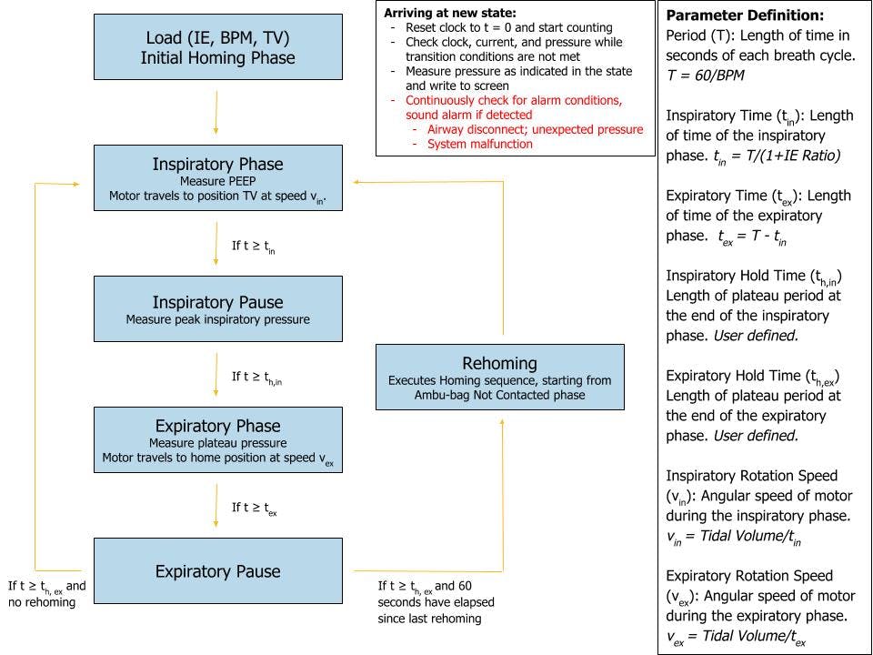
Homing Procedure
The Compression Arm is sprung upwards such that it mechanically hinges open and depresses the absolute limit switch (hard stop) when not actively pulled downward by the pulley and rope. On startup, the arm actively moves upward, away from the Ambu-bag if present, to the hard stop (by unspooling the rope until the switch is depressed), and the encoder homes (zeroes). From this known angle, the Compression Arm position is calibrated with a soft stop (a maximum angle) corresponding to the Compression Arm being in the fully horizontal position.
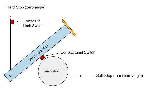
When the operator chooses to insert a new Ambu-bag, or replace the current one, they select the appropriate workflow on-screen. The Compression arm is raised to its maximum position (hitting the absolute limit switch and re-zeroing the machine). The operator inserts/replaces the Ambu-bag and confirms having done so on-screen. The compression arm moves down until the arm depresses the contact limit switch (when the arm has just contacted the Ambu-bag). The control software registers the inserted bag's diameter, confirms on-screen, and generates appropriate volume control mappings.

Next: |
Want to print your doc?
This is not the way.
This is not the way.

Try clicking the ··· in the right corner or using a keyboard shortcut (
CtrlP
) instead.