Start
This document provides information for both SD and VTA laser cutting.
Please refer to the page outline (to the right) for quick reference.
This document includes:
An overview of the machines at either office. Links to relevant tutorials and guides from Epilog Laser. How to export for printing (From Revit, AutoCAD and Rhino). How to process files and send to print via Adobe Illustrator. Note: Inside this document orange text indicates Ventura Office specific information. Green text indicates San Diego Office specific information. The Laser Cutters
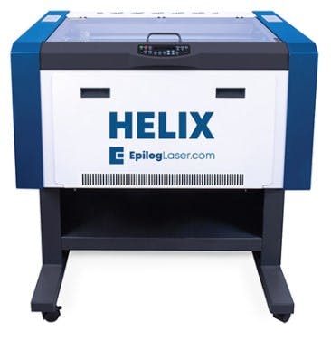
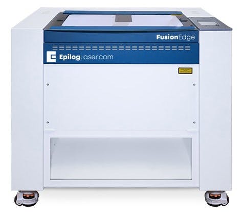
RNT currently has two laser cutters: An Epilog Helix Laser 30 Watt at the Ventura Office and a Epilog Fusion Edge Laser 30 Watt at the San Diego Office. Both of these machines operate in a similar manner. If you become comfortable on one, you will have a good grasp of how either functions.
Both RNT Epilog lasers are carbon dioxide laser cutters. In a Co2 laser cutter, light is produced when electricity runs through a gas-filled tube with mirrors at both ends. One mirror is fully reflective while the other one lets some light come through. These mirrors guide the laser beam into the material that is to be cut.
Any light produced by Co2 lasers is extremely powerful. This is because of the mirrors that bookend the tube of gases. These mirrors reflect most of the light traveling through the tube and cause the light waves to build in intensity. The light only passes through the partially reflective mirror when it becomes bright enough.
Epilog Helix Laser 30 Watt
Ventura has a Helix Laser 30 Watt. This cutter has a max bed size of 24.0 L x 18.0 W x 8.5 H in. More information from Epilog Laser can be found here: Epilog Fusion Edge Laser 30 Watt
San Diego has a Epilog Fusion Edge Laser 30 Watt. This cutter has a max bed size of 24.0 L x 24.0 W x 10.0 H in. More information from Epilog Laser can be found here:
File Type Overview
In order to laser cut something, you must first convert linework into vectors and/or raster images.
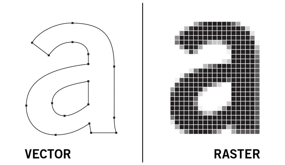
Vector files are images that are made up of mathematical formulas and calculations. They are made up of lines and shapes that can either follow straight or curved paths. Vector files are like a map that provides a distinct path with lines and coordinates that the laser machine should follow. They are not made up of pixels and thus are not affected by resolution. Therefore, the size of the images can be adjusted infinitely, and they will always appear clear and crisp. Several vector file formats are available for use when it comes to laser cutting/engraving. They include: AI (Adobe Illustrator) – one of the most popular vector file formats used in laser cutting. It is common for cutting shapes and designs, or engraving graphics such as logos. It is used with Adobe Illustrator software. SVG (Scalable vector graphics) – it is used to create graphic images that can be size-adjusted while remaining smooth and clean. It can be used with SVG Edit. CDR (CorelDraw) – It is used with CorelDraw or other Corel programs. DXF (Drawing Exchange Format) – popularly known as AutoCAD DXF, it is a CAD file developed by Autodesk. DXF files are ideal if you are looking to create mechanical parts or metal fabrication projects (laser cut signs, etc.). DWG (DRAWING) – a CAD vector file used for creating 2D or 3D designs. Raster files, also known as bitmap, are graphic images that are made up of pixels. The pixels contain tonal information and unique colors. Together, these pixels add up to create the image you see when displayed on a computer, paper, or other surfaces. Since raster files are made up of pixels, their clarity is dependent on resolution. If you zoom in on a raster image, you will start seeing tiny squares (the pixels) as the image increases in size. This is the main difference between raster and vector files. Raster files are used in laser engraving or laser etching (marking). However, it is possible to and then use them for laser cutting. When it comes to raster or bitmap files, several formats are available. They include: JPEG (Joint Photographic Expert Group) – one of the most popular raster image files. However, it tends to compress images, leading to pixel loss. GIF (Graphics Interchange Format) – a raster file format that only supports up to 256 colors. Mainly used for creating animation images. PNG (Portable Network Graphics) – was designed to replace GIF files in terms of color options (48-bit color options). PNG files also have the added advantage of lossless compression TIFF (Tagged Image File Format) – popular with commercial printing since it supports Photoshop’s program features while creating lossless compression images. While vector and raster files are the most popular, some files can store both vector and raster graphics. These include: EPS (Encapsulated PostScript) – a graphic file image that can be found on the Adobe Illustrator software. It is mainly used to create 2D vector images, but can also store text and bitmap images. PDF (Portable Document Format) – It can either be vector or raster depending on the software program used. For example, Adobe Illustrator or CorelDraw will create vector PDF files. On the other hand, Photoshop and Corel Paintshop will create raster files Export Process
Laser cutting in either office will require the general three step process diagrammed above. STEP 1 involves generating the linework in one of the three most popular software programs RNT uses. STEP 2 involves processing the linework with an Epilog-compatible vector software which in our case, is Adobe Illustrator. From here, the Epilog software is used for STEP 3 to perform the laser cut job.
General considerations and things to know when preparing a laser cut file:
Know the scale needed for the physical model in comparison to the scale of your digital model. Know the thickness of the material that will be used for your physical model. This thickness will need to be considered when laying out the linework. Make sure the material that is planned to be used can be laser cut.
First you need to load the titleblock template that corresponds to the laser cutter that you are using (SD or VT). Revit Laser Cutter Templates can be found in the RNT SharePoint. To have these accessible in your Revit file you will need to add a shortcut/synchronize the SharePoint folder that these templates live in to your OneDrive (if you have not already). In SharePoint Studio>Library>_Revit>TitleblocksIn OneDrive (once folder shortcut is added or folder is synchronized) To load the sheet you will right click on “Sheets (BY SET)” in the project browser and click on “New Sheet...”Then, you will click on “Load...” and the Load Family dialogue box will pop up. Here you will be able to browse the OneDrive and find the laser cutter template family that you need. For this tutorial, I will be working with the “Laser Cutter VT 18x24” template.Once loaded, I moved the sheet to the schematic design set and renamed it “LC-1-Laser Cut Example.” Now you are ready to place any drawings that you will be laser cutting on the sheet. For this example, I have made linework that will capture the laser cutter’s main capabilities. In the example above I have included a black scale and a north arrow that will be processed as bitmap data. The other lines are in 4 main colors which will correspond to different laser intensities. The office standard with these 4 main colors will be the following: Further information and description related to the colors will be covered in STEP 2 and STEP 3. For now, It is important to know that assigning these colors to your linework will make the next steps quicker. We encourage you to figure out and assign the corresponding colors to the linework in Revit. I will continue this tutorial with the assumption that this has been done. (The alternative would be assigning colors in Adobe Illustrator)
Once your sheet is populated with the linework you will be laser cutting, you will then print to Bluebeam PDF with the settings circled below. If using the SD laser cutter, the paper size will be “ARCH_D_(24.00x36.00_Inches)” since there is no 24”x24” preset. This is okay as we will be refining the linework and sheet size in Adobe Illustrator. Save to desired destination. Elements such as text may be subject to unwanted transformation when saved PDF file is opened in Adobe Illustrator. First you need to load the template that corresponds to the laser cutter that you are using (SD or VT). AutoCAD Laser Cutter Templates can be found in the RNT SharePoint. To have these accessible in your AutoCAD file you will need to add a shortcut/synchronize the SharePoint folder that these templates live in to your OneDrive (if you have not already). In SharePoint Studio>Library>AutoCAD>Templates In OneDrive (once folder shortcut is added or folder is synchronized) To load the template you will right click on the “Layout 1” tab (make a new layout if needed). Then click on “From Template...”The Select Template From File dialogue box will pop up. Here you will be able to browse the OneDrive and find the laser cutter template family that you need. For this tutrial, I will be working with the “Laser Cutter VT 18x24” template. Now you are ready to fit any drawings that you will be laser cutting on the extents of the sheet. For this example, I have made linework that will capture the laser cutter’s main capabilities. In the example above I have included a black scale and north arrow that will be processed as bitmap data. The other lines are in 4 main colors which will correspond to different laser intensities. The office standard with these 4 main colors will be the following: Further information and description related to the colors will be covered in STEP 2 and STEP 3. For now, It is important to know that assigning these colors to your linework will make the next steps quicker. We encourage you to figure out and assign the corresponding colors to the linework in AutoCAD. I will continue this tutorial with the assumption that this has been done. (The alternative would be assigning colors in Adobe Illustrator)
Once your sheet is populated with the linework you will be laser cutting, you will then print to Bluebeam PDF with the settings circled below. If using the SD laser cutter, the paper size will be “ARCH_D_(24.00x36.00_Inches)” since there is no 24”x24” preset. This is okay as we will be refining the linework and sheet size in Adobe Illustrator. Save to desired destination. Elements such as text may be subject to unwanted transformation when saved PDF file is opened in Adobe Illustrator. First you will get your linework grouped up and ready on the “Top” view. Make sure the linework is as close as you can get it to the file origin (0,0,0). In the example above I have included a black scale and north arrow that will be processed as bitmap data. The other lines are in 4 main colors which will correspond to different laser intensities. The office standard with these 4 main colors will be the following: Further information and description related to the colors will be covered in STEP 2 and STEP 3. For now, It is important to know that assigning these colors to your linework will make the next steps quicker. We encourage you to figure out and assign the corresponding colors to the linework in Rhino. I will continue this tutorial with the assumption that this has been done. (The alternative would be assigning colors in Adobe Illustrator)
Once you have complete the linework and are in the “Top” view, you will then highlight all linework. With the linework highlighted, you will go to “File” and “Export Selected...”The “Export” dialogue box will pop up. Save to desired location as an Adobe Illustrator file.Once saved to desired location, the “AI Export Options” dialogue box pops up. Here you can adjust the shown parameters as needed. Elements such as text may be subject to unwanted transformation when saved AI file is opened in Adobe Illustrator. Autodesk Revit and Autodesk AutoCAD First, you will need to locate the Adobe Illustrator laser cutter templates which can be found on SharePoint as shown below. You may want to add a shortcut/synchronize this folder to your OneDrive or if preferred, downloading to your desktop is also an option. Open the template and save the file with desired name. For the purposes of this tutorial, I will be using the VT laser cutter template. Once opened, go to file and click on “Place...” Then browse and find the PDF from the Revit/AutoCAD file export. Place this on the sheet. Once placed, right click on the placed object and click on “Ungroup.” Right click on the object again and click on “Release Clipping Mask.” This will free up the individual line vectors and have them available for manipulation and sorting. IMPORTANT: the PDF boarder will show up as a set of invisible lines on the boarder of the Illustrator sheet so it is crucial for you to delete these before continuing. Otherwise, the laser cutter will read these as cut data. You will then want to move the lines to the corresponding layers based on color. For this example I am clicking on the red line. Once the red line is highlighted, go to “Select”>”Same”>”Stroke Color”. This will then select all lines colored in red.Red lines will be selected. Click on the “Cut” layer to highlight it. Now right click on the selection and go to “Arrange”>”Send to Current Layer.” This will move all the red lines to the “Cut” layer. Repeat the same process for all the other colors in the file. Scale bar and north arrow will be processed in STEP 3. First, you will need to locate the Adobe Illustrator laser cutter templates which can be found on SharePoint as shown below. You may want to add a shortcut/synchronize this folder to your OneDrive or if preferred, downloading to your desktop is also an option. Open the template and save the file with desired name. For the purposes of this tutorial, I will be using the VT laser cutter template. Open the Illustrator file exported from Rhino. You will get the following message if you have text. Click on “Update.” Then save the updated file. You can replace the file if desired. You will not need to do this step if there is no text in your Rhino exported Illustrator file. Go back to the template file. Go to file and click on “Place...” Then browse and find the saved Illustrator file from the Rhino file export. Place this on the sheet. Once placed, right click on the placed object and click on “Ungroup.” Right click on the object again and click on “Release Clipping Mask.” This will free up the individual line vectors and have them available for manipulation and sorting. IMPORTANT: the PDF boarder will show up as a set of invisible lines on the boarder of the Illustrator sheet so it is crucial for you to delete these before continuing. Otherwise, the laser cutter will read these as cut data. You will then want to move the lines to the corresponding layers based on color. For this example I am clicking on the red line. Once the red line is highlighted, go to “Select”>”Same”>”Stroke Color”. This will then select all lines colored in red.Red lines will be selected. Click on the “Cut” layer to highlight it. Now right click on the selection and go to “Arrange”>”Send to Current Layer.” This will move all the red lines to the “Cut” layer. Repeat the same process for all the other colors in the file. Scale bar and north arrow will be processed in STEP 3. The Epilog Laser software can only read vector linework if the lines are 0.001 stroke size and in RGB document color mode. To quickly make sure that the vector linework is the correct size and color, I have provided lines in the Key that you can use the eye dropper tool on. This tool allows one to copy the needed vector line parameters to the imported linework. I will be using the “Cut” layer in this example. To use the eye dropper tool, you will first select everything in the “Cut” layer by clicking on the white circle to the right of the layer name. Then click on the eyedropper tool. Once the eye dropper tool is activated, you will click on the red vector line in the Key. This will give the imported linework the necessary parameters. Simply repeat for the other colors. The laser cutter will automatically light engrave the material if it reads any other color not provided in the key. Ventura: Helix Laser 30 Watt INSTRUCTIONS WILL BE UPDATED SOON! for now, please use the following: San Diego: Epilog Fusion Edge Laser 30 Watt SD Instruction start here Material Capabilities Table

 Laser Cutters


