Skip to content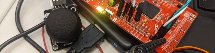
Get the position of the joystickBased on the position of the joystick, generate corresponding PWM signal and output to the servo motor.
Joystick at GNDJoystick not movingJoystick at +Vcc
Assignment 1 - MSP432 Microcontroller I/O Programming
338713 Hong-Bin YANG
Introduction
The goal of this project is to control a servo motor by a joystick through a MSP432 microcontroller. The overall approach is as following:
The details will be described in order in the following paragraph.
Method
Reading the Joystick’s Position
The joystick’s position can be read through an ADC. To set up the ADC, we need to set a PIN as input and a corresponding interrupt. When the ADC is triggered, finishes converting, and put the value in the MEM[0] the ADC14_IRQHandler() is called to modify the PWM.
The position of the joystick is represented by a value from 0x0000 to 0x3FFF (i.e. from GND to+Vcc). When the joystick is not moved, the value would be 0x1FFF.
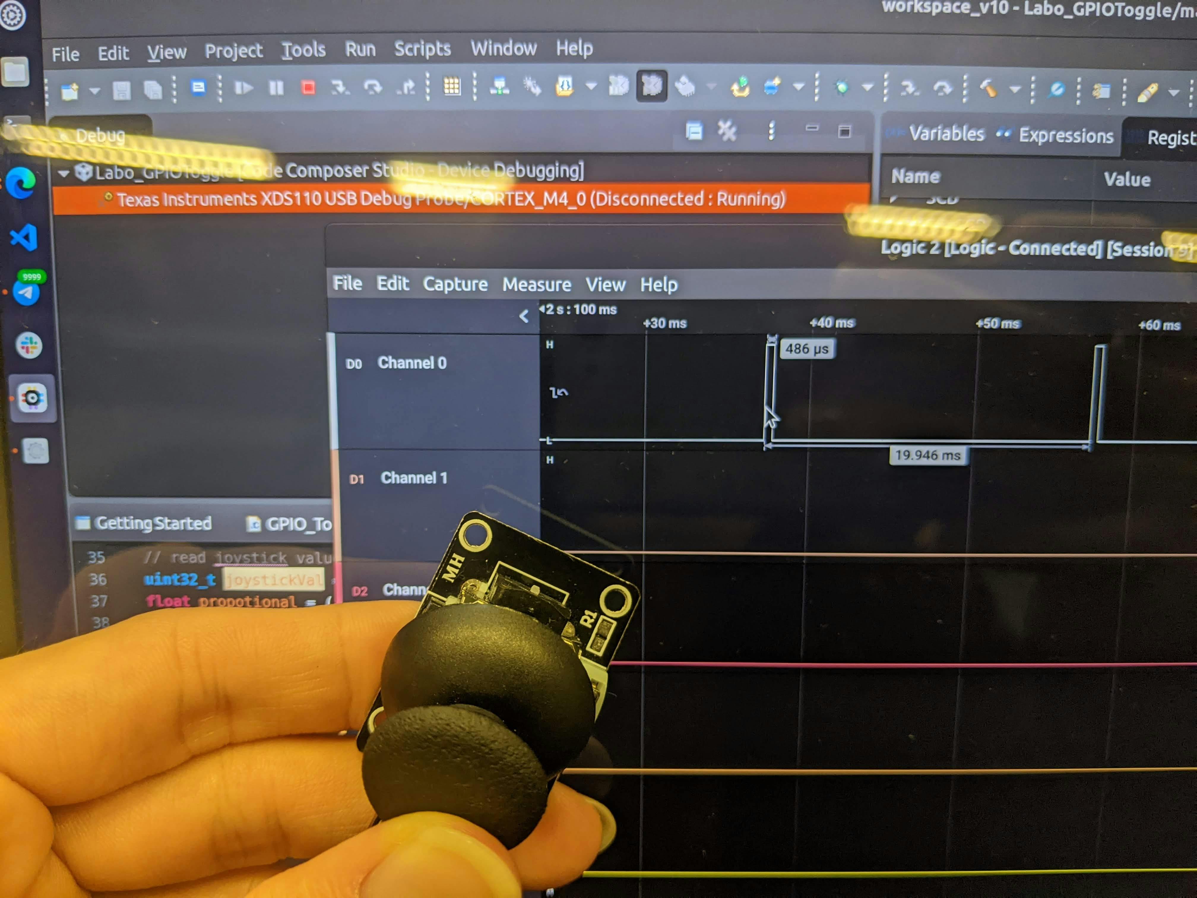
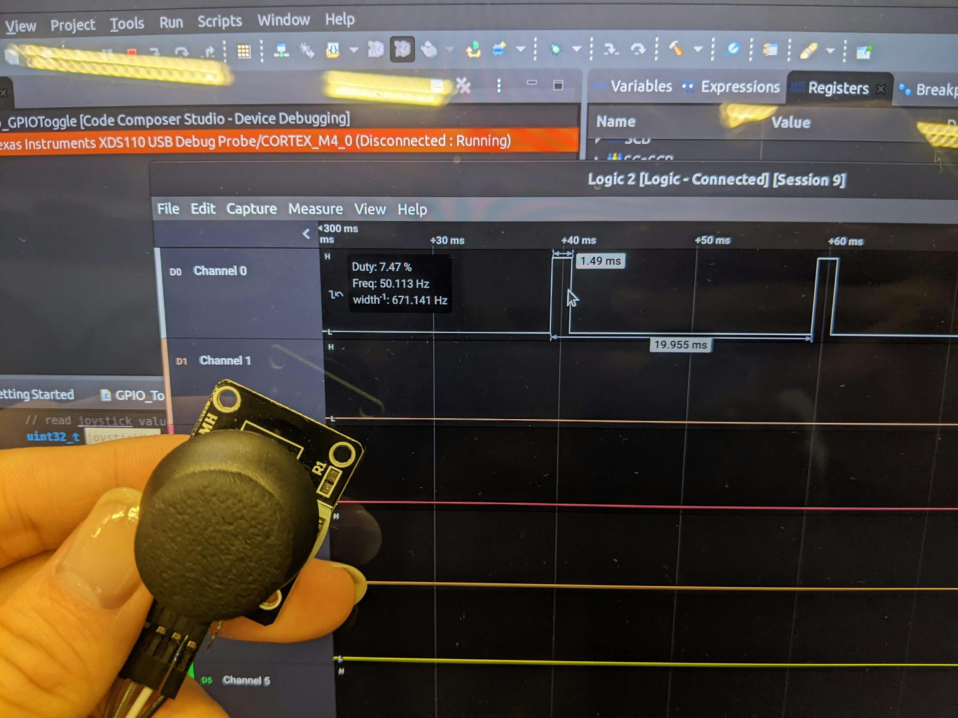
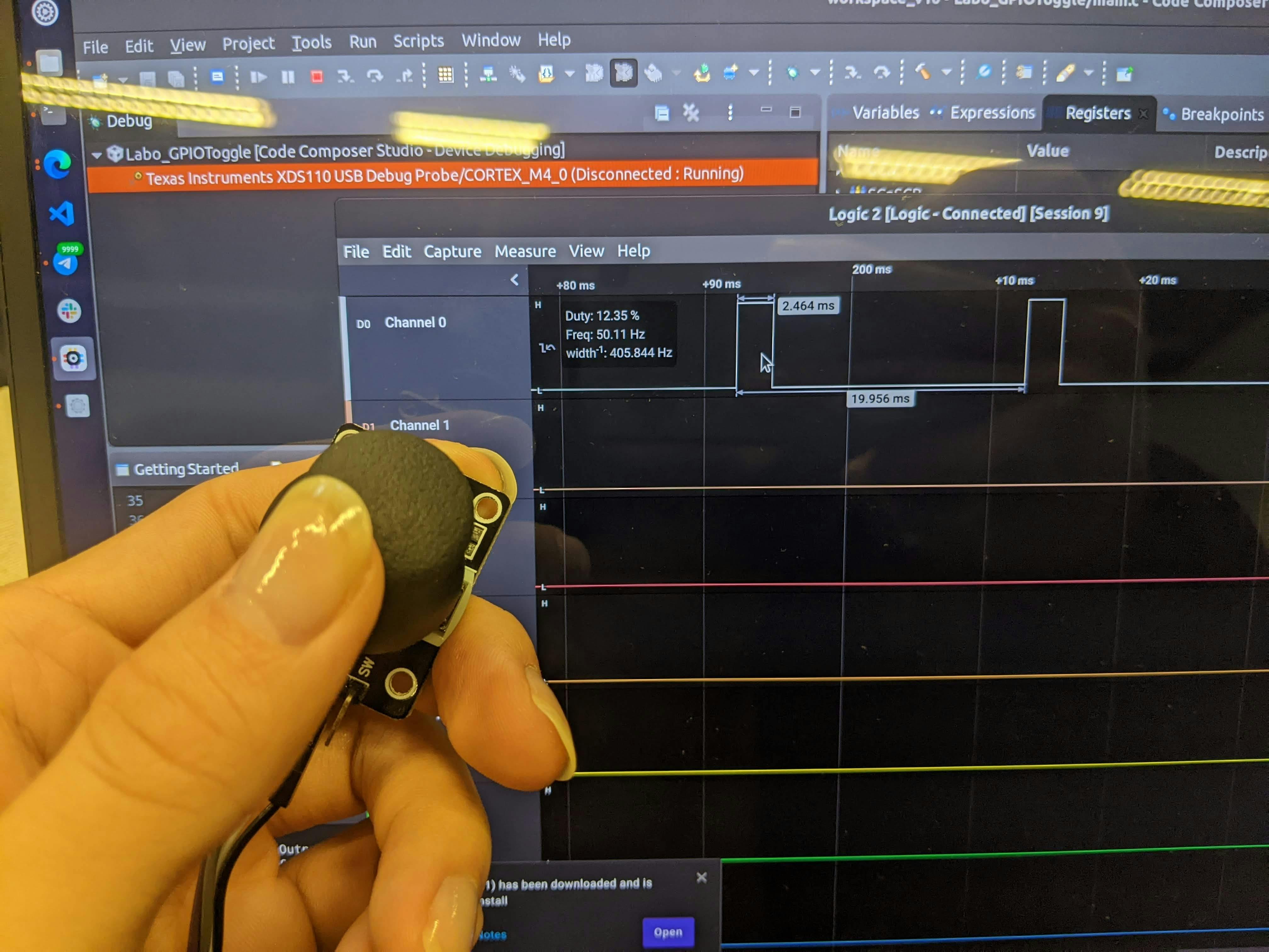
The angle of the servo motor is determined by the duty of a PWM signal. After experiment, I found that using a PWM of 0.5~2.5ms/20ms works the best. That means, when the value of the joystick’s position is 0x0000, a pulse of 0.5ms would be generated, and when the value is 0x3FFF, a pulse of 2.5ms would be generated.
void initADC()
{
// select P4.0 as A13
P4->DIR |= 0x00;
P4->SEL0 |= 1 << 0;
P4->SEL1 |= 1 << 0;
ADC14->MCTL[0] = ADC14_MCTLN_INCH_13;
// set up ADC14
ADC14->CTL0 = ADC14_CTL0_ON;
ADC14->CTL0 |= ADC14_CTL0_SSEL_2; // set timer source to ACLK
ADC14->CTL0 |= ADC14_CTL0_CONSEQ_2; // Repeat single channel
ADC14->CTL0 |= ADC14_CTL0_SHP; // using sample timer
ADC14->IER0 |= ADC14_IER0_IE0; // Enable interrupt for MEM[0]
ADC14->CTL0 |= ADC14_CTL0_ENC;
// enable interrupt
NVIC_EnableIRQ(ADC14_IRQn);
}
void ADC14_IRQHandler(void)
{
// clear interrupt flag
ADC14->CLRIFGR0 = ADC14_CLRIFGR0_CLRIFG0;
// read joystick value
uint32_t joystickVal = ADC14->MEM[0];
float propotional = (float)joystickVal / (float)0x3FFF * 2;
// set PWM for servo motor
setPWM(0.5f + propotional);
}
To continuously update the value, an interrupt which triggers the ADC is set to run every 100ms.
void initInterrupt()
{
// Init Timer A1 is for trigger ADC converter to read
TIMER_A1->CTL = TIMER_A_CTL_SSEL__ACLK | TIMER_A_CTL_MC__UP;
// Init for interrupt
TIMER_A1->CCTL[0] |= TIMER_A_CCTLN_CCIE;
NVIC_EnableIRQ(TA1_0_IRQn);
// set trigger period
TIMER_A1->CCR[0] = ms2ticks(ADC_TRIGGER_PERIOD);
}
void TA1_0_IRQHandler(void)
{
// Reset interrupt flag
TIMER_A1->CCTL[0] &= 0xffff ^ (1 << TIMER_A_CCTLN_CCIFG_OFS);
ADC14->CTL0 |= ADC14_CTL0_SC;
}
Controlling the servo motor
To output the PWM to the servo motor, a timer is set to set/reset mode, and the corresponding GPIO is set to use it as the output.

In the set/reset mode, it would be set to high when the timer count to CCR[0] and output low at CCR[1]. When the ADC reads an output, it calls setPWM(float width) to change the value of CCR[1], so the pulse’s width is changed.
void initPWM(){
// set the corresponding GPIO to use the timer as output
P2 -> DIR = 0xFF;
P2 -> SEL0 = 1 << TARGET_PIN_MOTOR;
P2 -> SEL1 = 0 << TARGET_PIN_MOTOR;
TIMER_A0->CCR[0] = ms2ticks(20.0f);
TIMER_A0->CCR[1] = ms2ticks(1.5f);
TIMER_A0->CTL = TIMER_A_CTL_SSEL__ACLK | TIMER_A_CTL_MC__UP;
TIMER_A0->CCTL[1] = TIMER_A_CCTLN_OUTMOD_7; // set/reset mode
}
void setPWM(float width){
TIMER_A0->CCR[1] = ms2ticks(width);
}
Main
Finally, the main function just call the three initialization functions and block in the end.
void main(void)
{
WDT_A->CTL = WDT_A_CTL_PW | WDT_A_CTL_HOLD; // stop watchdog timer
initInterrupt();
initPWM();
initADC();
while(1);
return 0;
}
Demo
hPWM
Want to print your doc?
This is not the way.
This is not the way.

Try clicking the ··· in the right corner or using a keyboard shortcut (
CtrlP
) instead.