Skip to content
Analysis and design of the static view of an application.Describe responsibilities of a system.Base for component and deployment diagrams.Forward and reverse engineering.
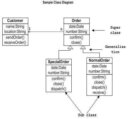
The name of the class diagram should be meaningful to describe the aspect of the system.Each element and their relationships should be identified in advance.Responsibility (attributes and methods) of each class should be clearly identifiedFor each class, minimum number of properties should be specified, as unnecessary properties will make the diagram complicated.Use notes whenever required to describe some aspect of the diagram. At the end of the drawing it should be understandable to the developer/coder.Finally, before making the final version, the diagram should be drawn on plain paper and reworked as many times as possible to make it correct.First of all, Order and Customer are identified as the two elements of the system. They have a one-to-many relationship because a customer can have multiple orders.Order class is an abstract class and it has two concrete classes (inheritance relationship) SpecialOrder and NormalOrder.The two inherited classes have all the properties as the Order class. In addition, they have additional functions like dispatch () and receive ().
Describing the static view of the system.Showing the collaboration among the elements of the static view.Describing the functionalities performed by the system.Construction of software applications using object oriented languages.
To capture the dynamic behaviour of a system.To describe the message flow in the system.To describe the structural organization of the objects.To describe the interaction among objects.
Objects taking part in the interaction.Message flows among the objects.The sequence in which the messages are flowing.Object organization.
To model the flow of control by time sequence.To model the flow of control by structural organizations.For forward engineering.For reverse engineering.
Modeling work flow by using activities.Modeling business requirements.High level understanding of the system's functionalities.Investigating business requirements at a later stage.
Share
Explore

Class Interaction Diagrams
Class diagram is a static diagram. It represents the static view of an application. Class diagram is not only used for visualizing, describing, and documenting different aspects of a system but also for constructing executable code of the software application.
Class diagram describes the attributes and operations of a class and also the constraints imposed on the system. The class diagrams are widely used in the modeling of objectoriented systems because they are the only UML diagrams, which can be mapped directly with object-oriented languages.
Class diagram shows a collection of classes, interfaces, associations, collaborations, and constraints. It is also known as a structural diagram.
Purpose of Class Diagrams
The purpose of class diagram is to model the static view of an application. Class diagrams are the only diagrams which can be directly mapped with object-oriented languages and thus widely used at the time of construction.
UML diagrams like activity diagram, sequence diagram can only give the sequence flow of the application, however class diagram is a bit different. It is the most popular UML diagram in the coder community.
The purpose of the class diagram can be summarized as −
How to Draw a Class Diagram?
Class diagrams are the most popular UML diagrams used for construction of software applications. It is very important to learn the drawing procedure of class diagram.
Class diagrams have a lot of properties to consider while drawing but here the diagram will be considered from a top level view.
Class diagram is basically a graphical representation of the static view of the system and represents different aspects of the application. A collection of class diagrams represent the whole system.
The following points should be remembered while drawing a class diagram −
The following diagram is an example of an Order System of an application. It describes a particular aspect of the entire application.
The following class diagram has been drawn considering all the points mentioned above.
Where to Use Class Diagrams?
Class diagram is a static diagram and it is used to model the static view of a system. The static view describes the vocabulary of the system.
Class diagram is also considered as the foundation for component and deployment diagrams. Class diagrams are not only used to visualize the static view of the system but they are also used to construct the executable code for forward and reverse engineering of any system.
Generally, UML diagrams are not directly mapped with any object-oriented programming languages but the class diagram is an exception.
Class diagram clearly shows the mapping with object-oriented languages such as Java, C++, etc. From practical experience, class diagram is generally used for construction purpose.
In a nutshell it can be said, class diagrams are used for −
Object Interaction Diagrams
From the term Interaction, it is clear that the diagram is used to describe some type of interactions among the different elements in the model. This interaction is a part of dynamic behavior of the system.
This interactive behavior is represented in UML by two diagrams known as Sequence diagram and Collaboration diagram. The basic purpose of both the diagrams are similar.
Sequence diagram emphasizes on time sequence of messages and collaboration diagram emphasizes on the structural organization of the objects that send and receive messages.
Purpose of Interaction Diagrams
The purpose of interaction diagrams is to visualize the interactive behavior of the system. Visualizing the interaction is a difficult task. Hence, the solution is to use different types of models to capture the different aspects of the interaction.
Sequence and collaboration diagrams are used to capture the dynamic nature but from a different angle.
The purpose of interaction diagram is −
How to Draw an Interaction Diagram?
As we have already discussed, the purpose of interaction diagrams is to capture the dynamic aspect of a system. So to capture the dynamic aspect, we need to understand what a dynamic aspect is and how it is visualized. Dynamic aspect can be defined as the snapshot of the running system at a particular moment
We have two types of interaction diagrams in UML. One is the sequence diagram and the other is the collaboration diagram. The sequence diagram captures the time sequence of the message flow from one object to another and the collaboration diagram describes the organization of objects in a system taking part in the message flow.
Following things are to be identified clearly before drawing the interaction diagram
Following are two interaction diagrams modeling the order management system. The first diagram is a sequence diagram and the second is a collaboration diagram
The Sequence Diagram
The sequence diagram has four objects (Customer, Order, SpecialOrder and NormalOrder).
The following diagram shows the message sequence for SpecialOrder object and the same can be used in case of NormalOrder object. It is important to understand the time sequence of message flows. The message flow is nothing but a method call of an object.
The first call is sendOrder () which is a method of Order object. The next call is confirm () which is a method of SpecialOrder object and the last call is Dispatch () which is a method of SpecialOrder object. The following diagram mainly describes the method calls from one object to another, and this is also the actual scenario when the system is running.

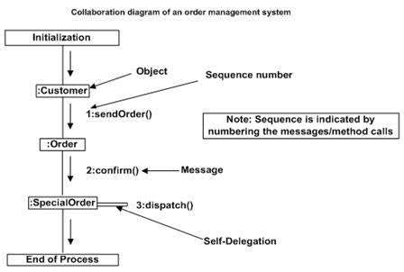
The Collaboration Diagram
The second interaction diagram is the collaboration diagram. It shows the object organization as seen in the following diagram. In the collaboration diagram, the method call sequence is indicated by some numbering technique. The number indicates how the methods are called one after another. We have taken the same order management system to describe the collaboration diagram.
Method calls are similar to that of a sequence diagram. However, difference being the sequence diagram does not describe the object organization, whereas the collaboration diagram shows the object organization.
To choose between these two diagrams, emphasis is placed on the type of requirement. If the time sequence is important, then the sequence diagram is used. If organization is required, then collaboration diagram is used.
Where to Use Interaction Diagrams?
We have already discussed that interaction diagrams are used to describe the dynamic nature of a system. Now, we will look into the practical scenarios where these diagrams are used. To understand the practical application, we need to understand the basic nature of sequence and collaboration diagram.
The main purpose of both the diagrams are similar as they are used to capture the dynamic behavior of a system. However, the specific purpose is more important to clarify and understand.
Sequence diagrams are used to capture the order of messages flowing from one object to another. Collaboration diagrams are used to describe the structural organization of the objects taking part in the interaction. A single diagram is not sufficient to describe the dynamic aspect of an entire system, so a set of diagrams are used to capture it as a whole.
Interaction diagrams are used when we want to understand the message flow and the structural organization. Message flow means the sequence of control flow from one object to another. Structural organization means the visual organization of the elements in a system.
Interaction diagrams can be used −
Activity Diagrams
The UML Activity diagram a format of UML Diagram used to visualize and plan the services delivered by a software application.
The Activity Diagram is used to describe the dynamic aspects of the system. That is, how the methods work together to deliver the use cases of the Application’s requirements.
Activity diagram is a flowchart to Visualize how the flow of information from one activity to another activity delivers a service.
The activity can be described as an operation of the system.
The control flow is drawn from one operation to another. Since operations are delivered as METHOD CALLS, the items in your Activity Diagram are METHODS. They will connect together, one method calling another, either with in the same class or between classes.
This flow can be sequential, branched, or concurrent.
Purpose of Activity Diagrams
The activity diagram captures the dynamic behavior of the system: The flow of method calls from one to another.
Activity is a particular operation of the system.
How to Draw an Activity Diagram?
The Activity diagram is suitable for modeling the activity flow of the system.
This means: modelling how methods in classes are connected and communicate. The difference between the Activity Diagram and the Object Interaction Diagram is:
The Object Interaction Diagram is structurally organized to emphasize the ORDER of how methods execute, first, second, third, ...
The Activity Diagram is drawn with METHODS placed in their Classes.
An application can have multiple systems. Activity diagram also captures these systems and describes the flow from one system to another. This specific usage is not available in other diagrams. These systems can be database, external queues, or any other system.
We will now look into the practical applications of the activity diagram. From the above discussion, it is clear that an activity diagram is drawn from a very high level. So it gives high level view of a system. This high level view is mainly for business users or any other person who is not a technical person.
This diagram is used to model the activities which are nothing but business requirements. The diagram has more impact on business understanding rather than on implementation details.
Activity diagram can be used for −
Want to print your doc?
This is not the way.
This is not the way.

Try clicking the ··· in the right corner or using a keyboard shortcut (
CtrlP
) instead.