Chapter: 06. Light
Light: Understanding How We See the World
What You Will Learn in This Chapter
By the end of this study, you will be able to:
Identify examples that show light travels in straight lines. Understand the principle, construction, and working of a pinhole camera. Explain what factors affect the size of the image in a pinhole camera. Describe how shadows are formed. Explain the occurrence of a lunar eclipse. Define and differentiate between the terms umbra and penumbra. The World of Light
Imagine a world without light – it would be absolute darkness! Light is essential for us to see the beautiful and colorful world around us. It is a form of energy that allows our eyes to sense vision. During the day, sunlight is our main source of light, making objects visible. At night, artificial sources like bulbs and tubelights help us see.
Luminous and Non-Luminous Objects
Objects can be categorized based on whether they produce their own light:
Luminous objects: These are objects that emit light of their own. Examples: The Sun, a candle, a lit bulb, a tubelight.
Fig. 6.1 Luminous objects Non-luminous objects: These objects do not produce their own light. They become visible only when they reflect light produced by a luminous object. Our eyes receive this reflected light, allowing us to see them. Examples: The Moon, a chair, a table, a ball, paper, the Earth.
Fig. 6.2 Non-luminous objects
Fig. 6.3 Reflection of light by a non-luminous object It’s interesting to note that a non-luminous object can sometimes be made luminous by heating it to a very high temperature. For example, an iron wire heated on a gas flame turns red hot and starts emitting light when its temperature reaches between 600° C to 800° C. This is how objects like heater coils or iron rods can become luminous.
Rectilinear Propagation of Light
Have you ever noticed how sunlight enters a dark room through a tiny opening, appearing to travel in a straight line? Or how the light from a cinema projector or car headlights seems to follow a straight path? These observations demonstrate a fundamental property of light: it travels in a straight line. This property is called rectilinear propagation of light.
Light continues to travel in a straight line unless it encounters an object that causes it to change direction.
Demonstrations of Rectilinear Propagation of Light
Here are ways to observe this property:
Using a Hollow Tube/Straw: Aim: To show that light travels in a straight line. Place a burning candle upright. Look at the candle flame through a straight hollow rubber tube or straw, keeping one eye closed. You will see the flame clearly. Now, bend the tube and try to view the flame again. You will not be able to see it. Observation: Flame is visible through a straight tube but not through a bent tube. Conclusion: This shows light travels in a straight line.
Fig. 6.4 Light travels in a straight line. Aim: To demonstrate rectilinear propagation of light. Take three square cardboard pieces of the same size and make holes in them at exactly the same level. Use wooden supports to make them stand straight on a table. Arrange the cardboards so that all holes are at the same height and aligned in a straight line. Place a burning candle at one end with its flame at the same level as the holes. Look through the holes from the other end. You will see the flame. Now, slightly move any one cardboard so the holes are no longer in a straight line. Observation: Flame is visible when holes are aligned but not when one cardboard is moved. Conclusion: This confirms that light travels in a straight line.
Fig. 6.5 Light travels in a straight line. Interesting Fact: Light itself is actually invisible! When you see a beam of sunlight streaming into a room, you are not seeing the light rays directly. Instead, you are seeing tiny dust particles in the air shining as light falls on them. These dust particles illuminate the path of the light, making it seem as if you are seeing the light itself. In a room free of dust, the path of light would be invisible.
Applications of Rectilinear Propagation of Light
The property of light traveling in a straight line has several important applications and explains many phenomena around us:
Natural shadows, such as eclipses Let’s explore each of these in detail.
Pinhole Camera
A pinhole camera is a very simple device that uses the principle of rectilinear propagation of light. It’s thought to have been invented in the 11th century in Arabic regions, originally for taking pictures of stationary objects. It creates an image through a tiny hole, called a pinhole.
Fig. 6.6 A pinhole camera Construction
A pinhole camera is built from a hollow rectangular box, which can be made of cardboard, metal, or wood.
Cut open one of the smaller sides of the box. Make a small hole in the middle of the opposite face of the box. This is the pinhole. Blacken the inside of the box. This is important to prevent any unwanted reflections of light inside the camera. Cover the open face (where you cut it open) with tracing paper or ground glass. This tracing paper acts as the screen where the image will form. Working
When an object (like a burning candle, labeled AB) is placed in front of the pinhole:
Light rays from the top point (A) of the object travel in a straight line through the pinhole and reach the bottom part of the screen at point A1. Similarly, light rays from the bottom point (B) of the object travel in a straight line through the pinhole and reach the top part of the screen at point B1. Because light rays travel in straight lines and cross at the pinhole, an inverted image (A1B1) of the object is formed on the screen.
Fig. 6.7 Image formed by a pinhole camera If a photographic film is used instead of tracing paper, a permanent image can be captured.
Characteristics of the Image Formed by a Pinhole Camera
The image produced by a pinhole camera has distinct characteristics:
Real: This means the image can be formed and seen on a screen. Inverted: The image appears upside down compared to the actual object. Size Variation: The image can be smaller than, larger than, or equal to the size of the original object, depending on certain factors. Important Note about Images: Sometimes you can see an image (like your reflection in a mirror), but it cannot be projected onto a screen. Such an image is called a virtual image. The image formed by a pinhole camera is real because it can be projected onto a screen.
Factors Affecting the Size of the Image
The size of the image formed by a pinhole camera depends on two main factors:
Distance between the screen and the pinhole (v): If the screen is moved closer to the pinhole, the image formed is smaller but appears brighter because the light is concentrated over a smaller area. If the distance between the screen and the pinhole increases, the image becomes larger but less bright, as the light spreads over a bigger area. For a standard pinhole camera, the length of the camera (distance between pinhole and screen) is usually fixed. Distance between the object and the pinhole (u): As the object is moved farther away from the pinhole, the size of the image decreases. As the object is moved closer to the pinhole, the size of the image increases.
Fig. 6.8 The size of the image depends on the position of the object with respect to the pinhole. The magnification of an image is defined as the ratio of the size of the image to the size of the object.
Effects of Pinhole Size and Shape on the Image
Shape of the pinhole: The shape of the pinhole does not affect the shape of the image formed. A square or triangular pinhole will still produce an inverted image similar to that from a round pinhole. Size of the pinhole: If the size of the pinhole is increased, the image formed will become blurred. This happens because a larger hole acts like many small pinholes grouped together. Each of these tiny “sub-pinholes” would produce its own image, and these images would overlap, resulting in a blurry overall image.
Transparent, Translucent, and Opaque Objects
Light cannot pass through all objects equally. Based on how much light passes through them, objects are classified into three categories:
Transparent objects: These objects allow light to pass through them completely. You can see clearly through them. Examples: Spectacles, spherical lenses, clear glass, air, pure water.
Fig. 6.9 Transparent object Translucent objects: Only a part of the light passes through these objects; the rest is absorbed or scattered. You can see light through them, but objects appear blurry or diffused. Examples: Frosted glass, butter paper, tracing paper, some plastics, cloudy water.
Fig. 6.10 Translucent object Opaque objects: Light does not pass through these objects at all. Instead, it is either reflected, absorbed, or scattered by the object. You cannot see through them. Examples: Wood, metals, cardboard, a wall, your body.
Fig. 6.11 Opaque object
Formation of Shadows
One of the most common effects of the rectilinear propagation of light is the formation of shadows.
When an opaque object is placed in the path of light, it blocks the light rays, preventing them from reaching the area behind the object. This creates a dark patch on a surface, like a wall, behind the object. This dark patch is called a shadow.
Opaque objects cast a dark and distinct shadow. Translucent objects cast a faint or blurred shadow, as some light passes through. Transparent objects cast no shadow at all because light passes right through them.
Fig. 6.12 Formation of shadow Shadow formation is an everyday occurrence. Your own shadow is visible when you walk in the sun, moving with you. Shadows are always formed in the direction opposite to the light source. As the Sun’s position changes throughout the day (from morning to evening), the size and direction of shadows also change:
Morning and Evening: Shadows are longer. Noon: Shadows are shortest. This variation in shadow length and direction is a direct consequence of light traveling in straight lines from a changing source.
Environmental & Health Note (from ECO-SOLDIER section):
Broken Compact Fluorescent Lamps (CFLs) emit mercury vapour, a toxic metal that can severely impact organs like the brain, lungs, and kidneys. Despite increasing demand for energy-efficient lights, the rise in CFL production has led to concerns, especially for waste workers who may experience restricted vision and difficulty judging distances due to mercury exposure. Reducing CFL use and promoting safer alternatives like LEDs can contribute to a healthier work environment and a cleaner environment, aligning with Sustainable Development Goal 8 (Protect labour rights and promote safe working environments).
Necessary Conditions for Shadow Formation
For a shadow to be formed, three conditions must be met:
A source of light: There must be light available to be blocked. An opaque object: This object must be placed between the light source and the screen to obstruct the light’s path. A screen or surface: A surface (like a wall, the ground, or a screen) is needed to receive the shadow, as shadows cannot form in thin air. Umbra and Penumbra
When an opaque object casts a shadow, the shadow often has two distinct regions:
Umbra: This is the central, darkest part of the shadow. It is the region that receives no light at all from the source. Penumbra: This is the region of partial darkness that surrounds the umbra. It receives some light from the source, making it lighter than the umbra but still darker than the fully lit area.
Fig. 6.13 Umbra and penumbra regions of a shadow Factors Affecting the Nature of the Shadow
The characteristics of the shadow (size, darkness) depend on several factors:
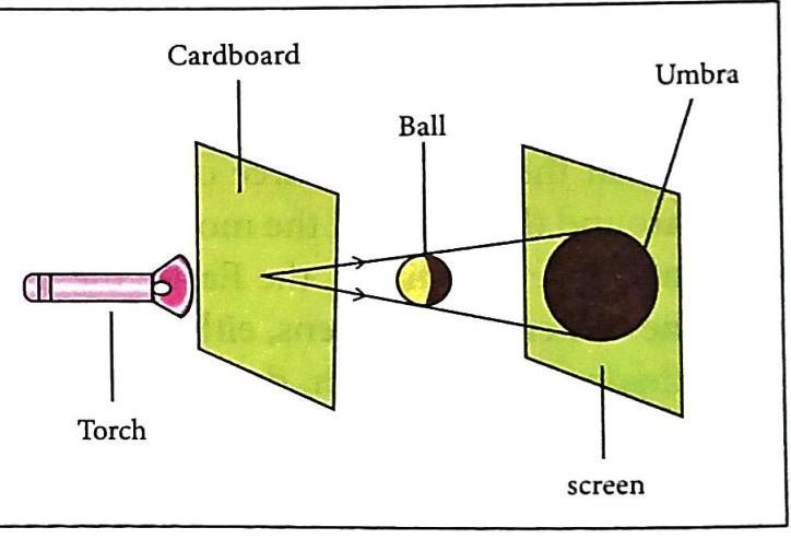
The shape of the object: The shadow will generally reflect the shape of the opaque object casting it (e.g., a ball’s shadow is different from a stick’s shadow). The size of the object: Larger objects tend to cast larger shadows, and smaller objects cast smaller shadows, assuming other factors are constant. The distance between the source of light and the object: As the object moves closer to the light source, its shadow increases in size because it blocks a larger area of the light. As the object moves farther from the light source, its shadow decreases in size. The distance between the object and the surface (screen) on which the shadow falls: As the object moves farther from the screen, the size of the shadow increases. As the object moves closer to the screen, the size of the shadow decreases. The nature of the source of light: Point source of light: A very small light source (like a tiny LED) tends to produce a shadow consisting of only the umbra (a totally dark region) on the screen. Extended source of light: A larger light source (like a torch or a bulb) produces a shadow with both an umbra (darkest central part) and a penumbra (lighter, partially dark surrounding region). Shadow Formation with Point and Extended Sources (Demonstration)
Aim: To show shadow formation with a point source and an extended source of light. Materials: A torch, cardboard, compass, tennis ball. Procedure for Point Source: Make a small hole in the cardboard with a compass. In a dark room, switch on the torch and point it at a wall. Place a tennis ball (larger than the hole) in front of the torch. Place the cardboard between the torch and the ball so light only reaches the ball through the small hole. Observation: The shadow formed on the wall consists only of the umbra (darkest region).
Fig. 6.14 Shadow formed by a point source of light Procedure for Extended Source: Remove the cardboard, allowing all light from the torch to fall on the tennis ball.  Self Study
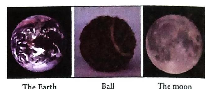
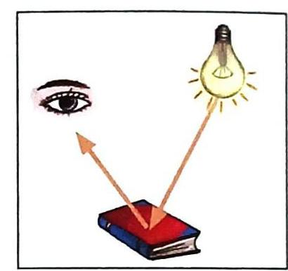


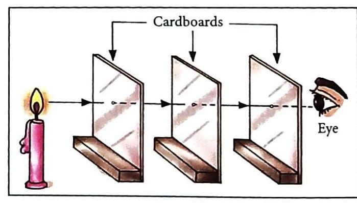

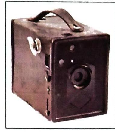
Fig. 6.6 A pinhole camera
Fig. 6.6 A pinhole camera
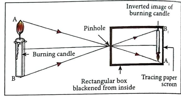
Fig. 6.7 Image formed by a pinhole camera
Fig. 6.7 Image formed by a pinhole camera


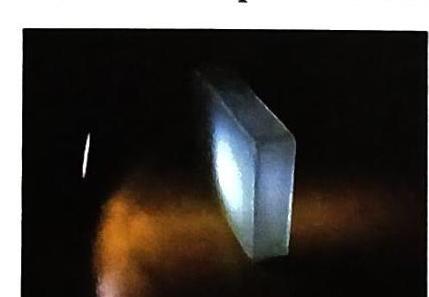

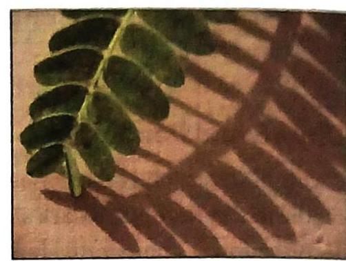
Fig. 6.12 Formation of shadow
Fig. 6.12 Formation of shadow
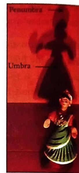
Fig. 6.13 Umbra and penumbra regions of a shadow
Fig. 6.13 Umbra and penumbra regions of a shadow
