Chapter: 05. Simple Machine
Simple Machines: A Journey into How Things Work!
What You Will Learn
By the end of this study, you will understand:
What a machine is and why we use them. The six main types of simple machines with real-life examples. Different kinds of levers and how they help us. What mechanical advantage means, especially for levers, and how to calculate it. Introduction to Machines
Imagine living in ancient times, when people relied only on their own strength or the strength of animals like bulls and horses to do work. Moving heavy objects, cutting wood, or lifting water was incredibly hard! But over time, humans discovered tools that made these tasks easier and faster. These tools are what we call machines.
For example, to cut fabric, we use scissors. To chop down a tree, we use an axe. Scissors and an axe are both examples of machines because they help us get work done more efficiently.
Advantages of Machines
Machines are super helpful in many ways. Here’s how they make our lives better:
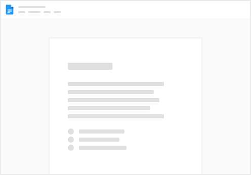
Less Effort: Machines allow us to do work with much less force. Example: A crowbar helps move a very heavy stone with less strain. A screw jack is used to lift a car for changing a flat tire.
Fig. 5.1 A screw jack Faster Work: They speed up tasks. Example: Garden scissors trim plant leaves much faster than using bare hands. A spade moves sand and earth quickly. Change in Force Direction: Machines can change the direction in which we apply force. Example: A pulley helps lift a pail of water from a well. You pull downwards, and the bucket moves upwards. Apply Force at a Convenient Point: They let us apply force in one spot to create an effect in another. Example: When hammering a nail, you hit the head of the nail (applying force at one end) to make the pointed end move into the wood.
Fig. 5.2 Hammering a nail Example: To open or close a door, you push or pull the handle, and the door moves around its hinges. Safety for Dangerous Work: Machines enable us to perform unsafe or dangerous jobs from a safe distance. Example: Fire tongs are used to safely lift a burning piece of coal from a fire, keeping your hands away from the heat.
Fig. 5.3 Fire tongs
Simple Machines
Simple machines are special types of machines that have very few parts. Their main job is to change the direction or the amount (magnitude) of the force we apply. They are usually operated by hand to perform mechanical work.
Examples: A claw hammer makes it easy to pull a nail out of wood. An axe helps cut wood easily. Both are simple machines. Sci-Vocab
Machines: Devices which make our work easier and faster. Simple Machines: Machines that are made up of very few parts and which simply change the direction or the magnitude of force or help us to work faster. Did You Know?
The word ‘machine’ comes from the Greek word ‘makhana’, meaning ‘device’. It was first used in English around 1540 to mean any kind of structure. By about 1670, it started to be used in its modern sense, describing equipment with multiple moving parts.
Fact Check: The Invention of Simple Machines
Myth: The Greek scientist and mathematician, Archimedes, invented the first simple machines.
Fact: While Archimedes was brilliant and developed and improved many simple machines, he didn’t invent them. The very first machines were invented by early human beings over 2 million years ago! These were basic stone tools like stone cores, hammerstones, and sharp stone flakes, used for cutting, chopping, or scraping.
Terms Associated with Simple Machines
To understand how simple machines work, we need to know some important terms:
Load (L): This is the weight of the object that needs to be lifted or moved. It’s the force that the machine has to overcome. Effort (E): This is the external force you apply to the machine to lift or move the load. Fulcrum (F): This is a fixed point around which the machine turns or pivots when it does work. Load Arm: This is the shortest distance from the load to the fulcrum. Effort Arm: This is the shortest distance from the effort to the fulcrum.
Fig. 5.4 Terms associated with simple machines Velocity Ratio (VR): This is the ratio of how far the effort moves compared to how far the load moves. \mathrm{VR}=\frac{\text { Distance moved by effort }}{\text { Distance moved by load }} Input: This is the energy supplied to a machine. It’s the work you do on the machine, like pushing a bicycle pedal. Output: This is what the machine does for you. It’s the work done by the machine, like the bicycle going fast or climbing a hill. Mechanical Advantage (MA): This describes how much easier a machine makes your work. It’s the ability of a machine to lift or move a large load with a small effort. It is calculated as the ratio of the load to the effort: \text { Mechanical advantage }(\mathrm{MA})=\frac{\text { Load }}{\text { Effort }} Since it’s a ratio of two forces (both measured in Newtons), Mechanical Advantage has no unit; it’s just a number. Sci-Vocab
Load: The weight to be lifted or moved by a machine. Effort: The external force applied to lift or move the load. Fulcrum: A fixed point about which the machine turns while doing mechanical work.
Types of Simple Machines
There are six main types of simple machines:
Lever
A lever is a rigid bar that can move freely around a fixed point called the fulcrum (F).
Have you ever used the end of a spoon to open a tight-fitting tin lid?
Fig. 5.5 Lever In this example:
The lid of the tin is the load. The edge of the tin where the spoon rests is the fulcrum. The force you apply to the other end of the spoon is the effort. Sci-Vocab
Lever: A rigid bar which can move freely about the fulcrum. More Examples of Levers:
Crowbar: Used to lift heavy stones. Here, the fulcrum is usually positioned between the load and the effort. Your Arm: Your arm acts as a lever, with your elbow as the fulcrum. A Door: A door can be thought of as a lever where the hinges are the fulcrum, the door’s weight is the load, and the force you apply to push it is the effort.
Law of Levers
Think about a seesaw. When you and your friend sit on opposite ends and it stays perfectly horizontal, the seesaw is balanced. If one side pushes down harder, it becomes unbalanced.
The Law of Levers describes this balance:
When a lever is balanced, the product of the load and the load arm is equal to the product of the effort and the effort arm.
\text { Load } \times \text { Load arm }=\text { Effort } \times \text { Effort arm }
Fig. 5.6 Law of levers We already learned that:
\text { Mechanical advantage }(\mathrm{MA})=\frac{\text { Load }}{\text { Effort }}
From the Law of Levers, we can rearrange the formula:
\text { Load } \times \text { Load arm } = \text { Effort } \times \text { Effort arm }
Divide both sides by “Effort” and “Load arm”:
\frac{\text { Load }}{\text { Effort }} = \frac{\text { Effort arm }}{\text { Load arm }}
So, Mechanical Advantage can also be given as:
\mathrm{MA}=\frac{\text { Effort arm }}{\text { Load arm }}
This means if the effort arm is longer than the load arm, the MA will be greater than 1, making it easier to lift the load.
Activity: Demonstrating the Law of Levers
This activity helps us see the Law of Levers in action:
Materials: Two rulers, a piece of paper, a pencil, tape, and six 5-rupee coins.
Procedure:
Cover one ruler with paper and balance it on a pencil. Tape the pencil to the ruler to stop it from slipping. The ruler acts as the lever, and the pencil is the fulcrum. Stack three 5-rupee coins on one side of the ruler. This is your “load.” The ruler will become unbalanced and tilt. Place one 5-rupee coin on the other side of the ruler. This is your “effort.” Slowly move the single coin (effort) until the ruler becomes horizontal and balanced again.
Fig. 5.7 To demonstrate the law of levers Using the other ruler, measure the distance of the stacked coins (load) from the fulcrum (load arm) and the distance of the single coin (effort) from the fulcrum (effort arm). If one 5-rupee coin weighs approximately 6 gf (grams-force), you can calculate the following: Load (weight of three coins) = 3 × 6 = 18 gf Effort (weight of one coin) = 1 × 6 = 6 gf Observation: You will find that:
Load × Load arm is approximately equal to Effort × Effort arm. Example Results Table (from repeating activity with different efforts):
Conclusion: For a balanced lever, Load × Load arm = Effort × Effort arm.
Types of Levers
Levers are categorized into three types based on the positions of the load, the effort, and the fulcrum.
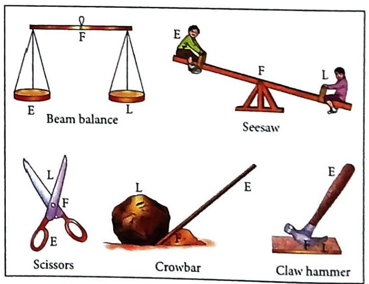
Lever of the First Order (Class One Lever)
Definition: The fulcrum (F) is located between the load (L) and the effort (E). Movement: The effort and the load move in opposite directions.
Fig. 5.8 Lever of the first order Beam balance
Fig. 5.9 Examples of levers of the first order Mechanical Advantage (MA): Can be greater than 1, equal to 1, or less than 1. If the effort arm is longer than the load arm, MA is greater than 1. This means a small effort can lift a large load (e.g., a crowbar). Lever of the Second Order (Class Two Lever)
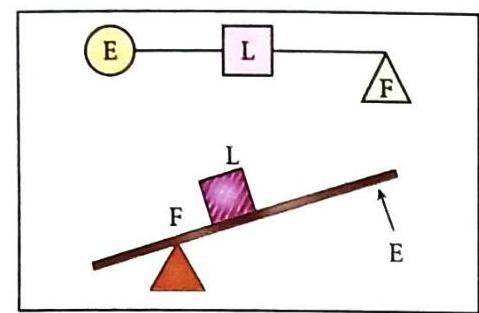
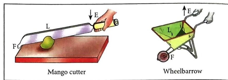
Definition: The load (L) is located between the fulcrum (F) and the effort (E). Movement: The effort and the load move in the same direction.
Fig. 5.10 Lever of the second order Bottle opener
Fig. 5.11 Examples of levers of the second order Mechanical Advantage (MA): Always greater than 1, because the effort arm is always greater than the load arm. Function: These levers always reduce the effort required, so they are called force multipliers. Lever of the Third Order (Class Three Lever)
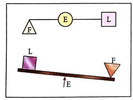
Definition: The effort (E) is located between the fulcrum (F) and the load (L). Movement: The effort and the load move in the same direction.
Fig. 5.12 Lever of the third order Human arm (lifting weight) Pair of tongs (like fire tongs or ice tongs) Spade
Fig. 5.13 Examples of levers of the third order Mechanical Advantage (MA): Always less than 1, because the effort arm is always shorter than the load arm. Function: These levers are often used for delicate tasks or to increase range of motion, like using forceps to pick up small objects. They do not multiply force; they require more effort than the load. Examples of Lever Calculations
Here are some worked examples to show how the formulas for levers are applied:
 Self Study
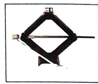
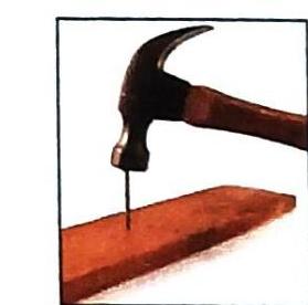
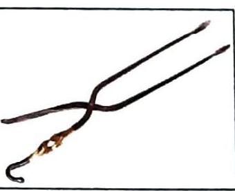

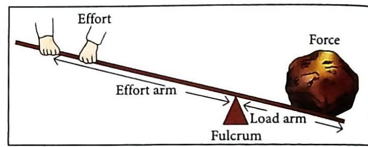
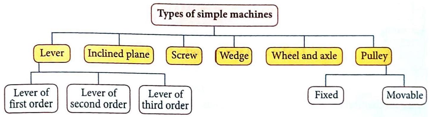
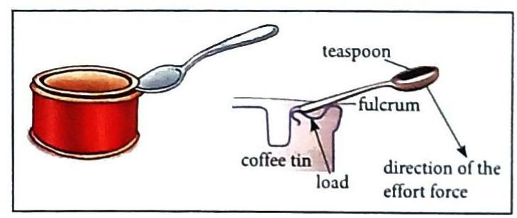
Fig. 5.5 Lever
Fig. 5.5 Lever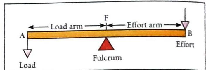
Fig. 5.6 Law of levers
Fig. 5.6 Law of levers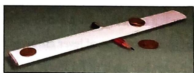

Conclusion: For a balanced lever, Load × Load arm = Effort × Effort arm.
Conclusion: For a balanced lever, Load × Load arm = Effort × Effort arm.