Skip to content
 Lab 10 - Motors and Controls
Overview
In this lab we are creating great things. This lab aimed to connect the DATX controller, FCU, and the parameters of all the associated parts together, and it succeeded in doing so. Though this lab took longer than intended, the results were satisfactory after much trial and error. The completion of the below tasks was paramount to the successful operation of the Believer UAS in the Spring, and the lab crew stopped at nothing to get it done. This lab paves the way for futher customization and optimization of the associated parts and parameters for the Believer drone.
Resources


There are no rows in this table
Parameters Version Control
Date
FCU Version
File
Notes
11/18/2025
1.27.1
Open
There are no rows in this table
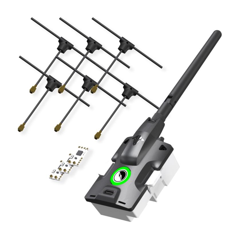
DATX
Connecting to any aircraft requires two things: transmitter and receiver. The Believer uses the controller as a User Interface for a third party transmitter rather than using the built in transmitter. The TBS Tracer Micro Starter set is what what used. To engage with these products, the first step was to obtain starter set. Then, the lab crew identified the items and ensured that all was there which was required. Finally, the lab crew soldered the appropriate parts and confirmed this with instructor. Images from this process can be seen below.

Soldering components in progress

Soldering final product
Pairing TX and RX
When the TX and RX are properly setup, they need to paired together to make them work. The lab crew was given an SD Card to insert into the DATX after all models were downloaded. When the crew plugged the SD card into the computer, they also saw that the instructor (so kindly) added all of the models, with one being “model00-model06.”
The crew then needed to flash the TX to version 6.17 using the TBS Agent Web. Once the crew flashed the firmware, they ensured that they connected to the “Tracer Micro TX.” They then selected the about column and ensured that there was a USER ID. This action was then shown to an instructor who confimed the setup.
At this point, the crew needed to use and upload model00 and model01, comparing the differences. There were be 3 differences. The crew changed “view: 1” to “view: 2” on models 01-06. This is the default view seen when piloting the aircraft, and view 2 gives one more data. As a point of note, a LUA Script provides a safer way to create behaviors for the autopilot. It does not mod core flight code within the receiver and is stored as scripts on an SD Card, which can be inserted into the controller. LUA allows operators to enter complex control algorithms, navigation systems, and data processing capabilities into a UAS system. It has the ability to run a wide range of programs, as well as, operate in various environments. It is lightweight and efficient making it valuable in UAS operation for remote control to autonomous flights.
The crew then plugged the RX into the BlueCube correctly. They then powered on the DATX, navigated to the LUA script, and went through the binding process. The crew ensured that TX and RX were in bind mode. The crew confirmed that they had successfully bound the two together. An image of the setup during this process can be seen below.

Component setup during pairing
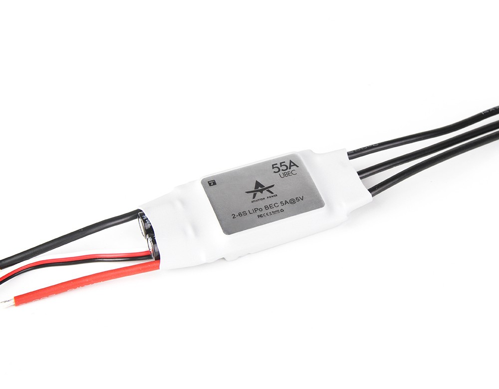
FCU and Parameters
In , the flight crew flashed the BlueCube with FCU Version 1.31. The FCU version and the parameters file currently used do not align, so uploading causes an error. Therefore, this had to be changed by uploading firmware and parameters. Following , the crew uploaded the FCU version provided (1.27.1). They then connected the flight controller to Ground Control and navigated to the Parameters tab. There they downloaded the parameters (which is always required to download the current parameters). Then, they exported the parameters as a file named parameters_PUB## where ## corresponds with the two digit group number. For this grouo, the number was “04.” This can be seen in the table above. The group then imported and uploaded the parameters file attached here: , and from the Engineering windows rebooted the autopilot. Finally, the lab crew exported the parameters again as a file named parameters_PUB## . The current FCU version is 1.27.
111025Dab10Parm - Modified.json
Next, the lab group set out to test system connectivity. With the new parameters uploaded, it’s important to test that all systems are green, and the lab group worked dilligently on this task. They thought to first connect the following sensors to the flight controller: GPS, airspeed sensor, telemetry, and DATX. Once that was complete, they verified that all systems were in the green and that the aircraft received GPS signal. A screenshot of the Platform Health Status can be seen below.

Platform Health Status Icons
Servos, ESC and Motors
Using the DAB010 model as a working guide, the crew developed a wiring table and notes for all connections including, telemetry, sensors, flight controls, and motors. This would then mirror DAB010 and be 100% complete and comprehensive. This was the only day that the sample platform would be available, and the lab crew was sure to collaborate with other groups to ensure a quality product. All remaining work was completed from the wiring notes and diagrams completed. The diagram group 4 helped to create is found on Draw IO and is linked below. Further down, wiring example images are shown.
Believer_Wiring_Diagram_111425.drawio.pdf
91 KB

An example of the wiring in the model aircraft

Reverse side of wiring example
After these actions were taken, the issues from the last lab became quite apparent. The reason why the GNSS was not operable was that the internals were not correctly arranged. The different firmware was flashed to be able to changed the parameters on the GPS unit itself, and this essentially worked to fix these issues. Custom Windracers parameters were used to help in this process, but the entire ordeal cost group 4 some time outside of the regular lab period. However, they banded together to make it work, and it paid off in the end because of the quality of the product produced.
Want to print your doc?
This is not the way.
This is not the way.

Try clicking the ··· in the right corner or using a keyboard shortcut (
CtrlP
) instead.