Skip to content
GPS
ESC
We used to upload model00 and model01 and compared the differences. There were 3 differences. We also changed “view: 1” to “view: 2” on models 01-06. This is the default view you see when piloting the aircraft and view 2 gives us more data.What is a LUA Script?
A set of written instructions written in the LUA programming language Why are we using one in this lab.
We are using it to adjust parameters on the TX module via the DATX (Transmitter) The 3 Differences:
a. Name was changed from: DAB010 to PUB01
b. Val changed from 10 to 1
c. View changed from 1 to 2
Connect the flight controller to Ground Control and navigate to the Parameters tab.Download the parameters (this is always required to download the current parameters).Export the parameters as a file named parameters_PUB## where ## corresponds with your two digit group number.Add the parameter file to the table above.Import and upload the parameters file attached: From the Engineering windows, reboot the autopilot.Export the parameters again as a file named parameters_PUB## Add the parameter file to the table above.
Connect the following sensors to the flight controller: GPS, airspeed sensor, telemetry, and DATX.Verify that all systems are in the green and that the aircraft gets GPS signal. Take a screenshot of the Platform Health Status window and the RC connection status in the top ribbon.This may require setting the system near a window with a clear view of the sky.
What is the current FCU version? This information is available in the status text window of Ground Control.Originally 1.31, but we have changed it back to 1.27Include a screenshot of your Platform Health Status.
Prepare and bind the DATX/TBS Tracer radio link,Make sure the FCU firmware version and parameter file matched the airworthy Believer standard,Verify that GPS, airspeed, telemetry, and RC input were all healthy in Ground Control, andUse a reference Believer (DAB010) to create wiring notes for servos, ESCs, and motors.
Connected the Blue Cube to Ground Control and checked the current firmware version.Flashed the FCU with the specified standard version (e.g., 1.27) matching the Believer reference platform.Downloaded the current parameters and saved them as a backup JSON file.Imported the provided modified parameter set for our group (e.g., parameters_PUB05.json) and uploaded it to the FCU.Rebooted the controller and exported the final parameters again so we had a record of exactly what was on the FCU.
RC link present (DATX/Tracer),GPS locked and showing satellites,Airspeed sensor responding,Telemetry connected to the ground station.
 Lab 10 - Motors and Controls
Overview
This lab focused on pairing the DATX transmitter with the BlueCube flight controller, uploading firmware and parameters, and verifying sensor connectivity to ensure reliable aircraft operation. During this lab, we also found the missing parameter that had prevented the GPS from working in lab 9 and created a wiring diagram for the Believer so that we know where everything will plug in when we build our aircraft.
Resources
GPS

ESC

There are no rows in this table
Parameters Version Control
Date
FCU Version
File
Notes
11/12/2025
1.27
Open
There are no rows in this table
The GPS issue in the previous lab occurred because the firmware on our test aircraft did not match the version running on the airworthy Believer. To fix this, we downgraded the firmware so that all platforms used the same, flight-proven version.
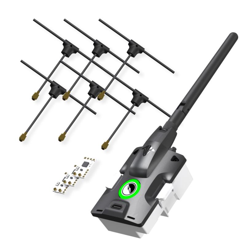
DATX

Antenna: Transmits and receives signals

Reciever: Receive signals from GCS or transmitter to allow for control of the aircraft, viewing of telemetry info, etc.

Servo Pins: Provides a physical connection between receiver and PWM cable to allow for signal transfer to and from the flight controller.
Then we soldered the servo pins to the receiver. This is a picture of the completed receiver:


Then we plugged in our RX into the BlueCube. Then we powered on our DATX and navigated to the LUA script and bound our RX to our TX module.
FCU and Parameters
In , we flashed the BlueCube with FCU Version 1.31. The FCU version and the parameters file we will be using do not align, so uploading causes an error.
Task: Upload Firmware and Parameters
To upload the firmware and parameters we used the following steps
Broken link
111025Dab10Parm - Modified.json
Broken link
Task: Test System Connectivity
With the new parameters uploaded, it’s important to test that all systems are green.
These are the steps we used to do that
Questions
Servos, ESC and Motors
Using the DAB010 model as a working guide, we developed a complete wiring diagram, table, and notes for all Believer connections, including telemetry, sensors, flight controls, and motors. The figure below shows the finalized wiring diagram for the Believer, with all wires correctly color-coded and labeled to mirror the DAB010 layout. On either side of the aircraft, the connector layouts for the detachable wings are shown, indicating how each wing harness plugs into the fuselage. It is critical that these connections are correct, because both the ESC controller leads and the aileron servo signals route through these wing connectors, and all remaining integration work will be completed using these wiring notes.

Individual Reflection
Overview of Lab
In this lab, our group brought together the Believer’s control system so that the DATX transmitter, TBS Tracer link, Blue Cube flight controller, and all major sensors could operate as a single, consistent system. The main goals were to
I was in Group 5 and worked primarily on the controls and configuration side: helping with the DATX/TBS Tracer setup, checking parameter uploads, and contributing to the wiring notes after we inspected the sample aircraft.
Procedures Completed – My Team’s Work
1. DATX / TBS Tracer Setup and LUA Model Changes
Our first task was to make sure the Believer control link used the TBS Tracer system correctly. We started by examining the contents of the Tracer starter kit—TX module, receiver, antenna, and servo pins—and confirmed how the receiver would eventually connect to the Blue Cube via PWM pins.
On the DATX side, we used the LUA scripts on the radio to edit the model files. We compared two model configurations using a diff tool so we could see exactly what needed to change. The main differences were the model name (e.g., from a DAB010 reference to our PUB## Believer), some value fields, and the default view used on the transmitter screen. We updated the model so that the telemetry view we wanted (View 2) would be the default, and the model name reflected our aircraft.
After that, we followed the Tracer binding procedure: powering the receiver, entering bind mode on the DATX through the LUA script, and waiting for the LEDs to confirm a successful bind. I was involved in stepping through the LUA menus, confirming that the settings matched the lab instructions, and verifying that the DATX could see the Tracer link.
2. FCU Firmware and Parameters – Version Control
Next, we focused on the flight controller firmware and parameters. In a previous lab, we had flashed a different FCU version, and this mismatch contributed to GPS issues. In Lab 10, we standardized on the correct FCU firmware version so that our parameter file would be compatible with the airworthy Believer configuration.
Following the lab procedure, we:
I helped manage the parameter download/export steps and double-checked that the filenames and version notes were accurate so our group could track what configuration was used on which date.
3. System Health and Wiring Notes
With the firmware and parameters in place, we connected GPS, airspeed sensor, telemetry, and the DATX/Tracer RC link to the FCU and opened the Platform Health / status view in Ground Control. As a group, we checked that all indicators were green:
When GPS did not lock immediately, we moved closer to a window and waited until satellites appeared, reinforcing the importance of testing in an environment where the sensor can actually see the sky.
Finally, using the DAB010 reference Believer, we traced the wiring from the FCU to the servos, ESCs, and motors. I helped take notes on which FCU outputs went to which surfaces (ailerons, elevator, rudder) and how the ESC and power wiring were routed. We turned these notes into a rough wiring diagram that we can rely on later when assembling or troubleshooting our own Believer.
Connection to Lab Objectives
This lab directly supported the objectives about motors and controls integration. The DATX/TBS Tracer work made the earlier conceptual questions about control links and radio models feel much more concrete. Editing the model files and using LUA scripts showed me why a standard transmitter configuration matters—if different pilots use different model setups for supposedly “identical” aircraft, it becomes much harder to fly and troubleshoot safely.
The firmware and parameter steps reinforced the idea of configuration management: the FCU version and parameter file must match. The GPS issues from the previous lab demonstrated how a small mismatch can break a critical subsystem, and Lab 10 showed how to fix that by aligning versions and logging our changes.
The wiring notes tied together the whole path from stick movement on the DATX to servo and motor motion on the aircraft. Seeing how each FCU output corresponds to a specific control surface or ESC helped me understand how the abstract “controls” section in the documentation maps to real hardware.
Reflection on the Lab
Before this lab, I tended to think of “motors and controls” as mostly a mechanical or ESC problem. After actually working with the DATX/TBS system, FCU firmware, and wiring, I realized that the control chain is only as strong as its weakest configuration step. A misconfigured model file, a mismatched firmware version, or unclear wiring can all lead to a situation where the aircraft doesn’t respond the way the pilot expects.
I also saw how important it is to keep good records—version tables for firmware and parameters, and clear wiring diagrams. When something doesn’t work, being able to say “this is the exact firmware build and parameter file we used on this date” makes troubleshooting much faster and safer. Without that information, we are guessing.
Overall, this lab made the Believer feel much more like a system I understand from end to end: from the DATX screen, through the TBS Tracer link, into the Blue Cube, and out to the servos, ESC, and motors. Going forward, I want to keep building the habit of treating configuration, version control, and wiring documentation as core parts of aircraft safety—not as optional paperwork to do at the end.
Want to print your doc?
This is not the way.
This is not the way.

Try clicking the ··· in the right corner or using a keyboard shortcut (
CtrlP
) instead.