Skip to content
What is a LUA Script?
A set of written instructions written in the LUA programming language Why are we using one in this lab.
We are using it to adjust parameters on the TX module via the DATX (Transmitter) The 3 Differences:
a. Name was changed from: DAB010 to PUB01
b. Val changed from 10 to 1
c. View changed from 1 to 2
Connect the flight controller to Ground Control and navigate to the Parameters tab.Download the parameters (this is always required to download the current parameters).Export the parameters as a file named parameters_PUB## where ## corresponds with your two digit group number.Add the parameter file to the table above.Import and upload the parameters file attached: From the Engineering windows, reboot the autopilot.Export the parameters again as a file named parameters_PUB## Add the parameter file to the table above.
Connect the following sensors to the flight controller: GPS, airspeed sensor, telemetry, and DATX.Verify that all systems are in the green and that the aircraft gets GPS signal. This is shown in the Platform Health Status window and the RC connection status in the top ribbon.This may require setting the system near a window with a clear view of the sky.
What is the current FCU version? This information is available in the status text window of Ground Control.Originally 1.31, but we have changed it back to 1.27Include a screenshot of your Platform Health Status.
 Lab 10 - Motors and Controls
Overview
During this lab we found the parameter that was missing that prevented the GPS from working in lab 9. During this lab we also made a wiring diagram for the Believer so that we know where everything plugs into when we build ours.
Resources


There are no rows in this table
Parameters Version Control
Date
FCU Version
File
Notes
11/13/2025
1.27
Open
There are no rows in this table
The reason that the GPS was not working last time was because the firmware version was different than the one that was currently on the airworthy Believer. That meant that we needed to downgrade the firmware version in order to standardize the firmware versions across all platforms and use a version that was proven to work.
DATX
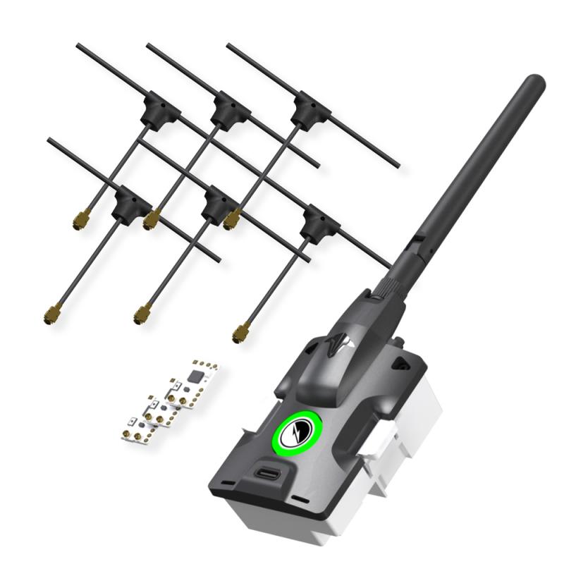
Connecting to any aircraft require two things. A transmitter and receiver. On our aircraft we are using the controller as a User Interface for a third party transmitter rather than using the built in transmitter. The TBS Tracer Micro Starter set is what we are using.
Items in Tracer Micro Starter Set
Name
Purpose
Picture
Antenna
Transmits and receives signals

Reciever
Receive signals from GCS or transmitter to allow for control of the aircraft, viewing of telemetry info, etc.

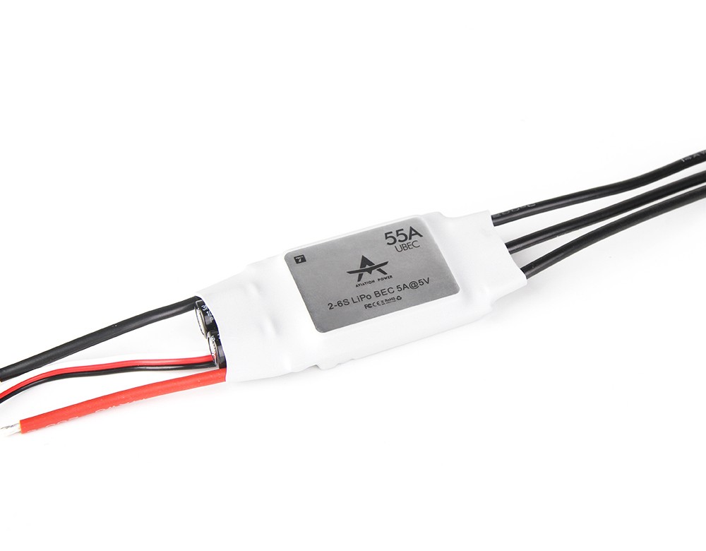
Servo Pins
Provides a physical connection between receiver and PWM cable to allow for signal transfer to and from the flight controller.

There are no rows in this table
Then we soldered the servo pins to the receiver. This is a picture of the completed receiver:


Pairing TX and RX
We used to upload model00 and model01 and compared the differences. There were 3 differences. We also changed “view: 1” to “view: 2” on models 01-06. This is the default view you see when piloting the aircraft and view 2 gives us more data.
Then we plugged in our RX into the BlueCube. Then we powered on our DATX and navigated to the LUA script and bound our RX to our TX module.
FCU and Parameters
In , we flashed the BlueCube with FCU Version 1.31. The FCU version and the parameters file we will be using do not align, so uploading causes an error.
Upload Firmware and Parameters
To upload the firmware and parameters we used the following steps
111025Dab10Parm - Modified.json
Test System Connectivity
With the new parameters uploaded, it’s important to test that all systems are green. These are the steps we used to do that
Questions
Servos, ESC and Motors
Below is a picture of the wiring diagram for the believer. All wires are color coded correctly. Also on either side of the aircraft is the layout for the connectors that plug into the wings. It is very important that these connections are correct as both the controller for the ESC and the aileron servo plug into here.
Wire Diagram:

Want to print your doc?
This is not the way.
This is not the way.

Try clicking the ⋯ next to your doc name or using a keyboard shortcut (
CtrlP
) instead.